Chapter 10 Appendix
POWER CON
PCON-CB/LC
241
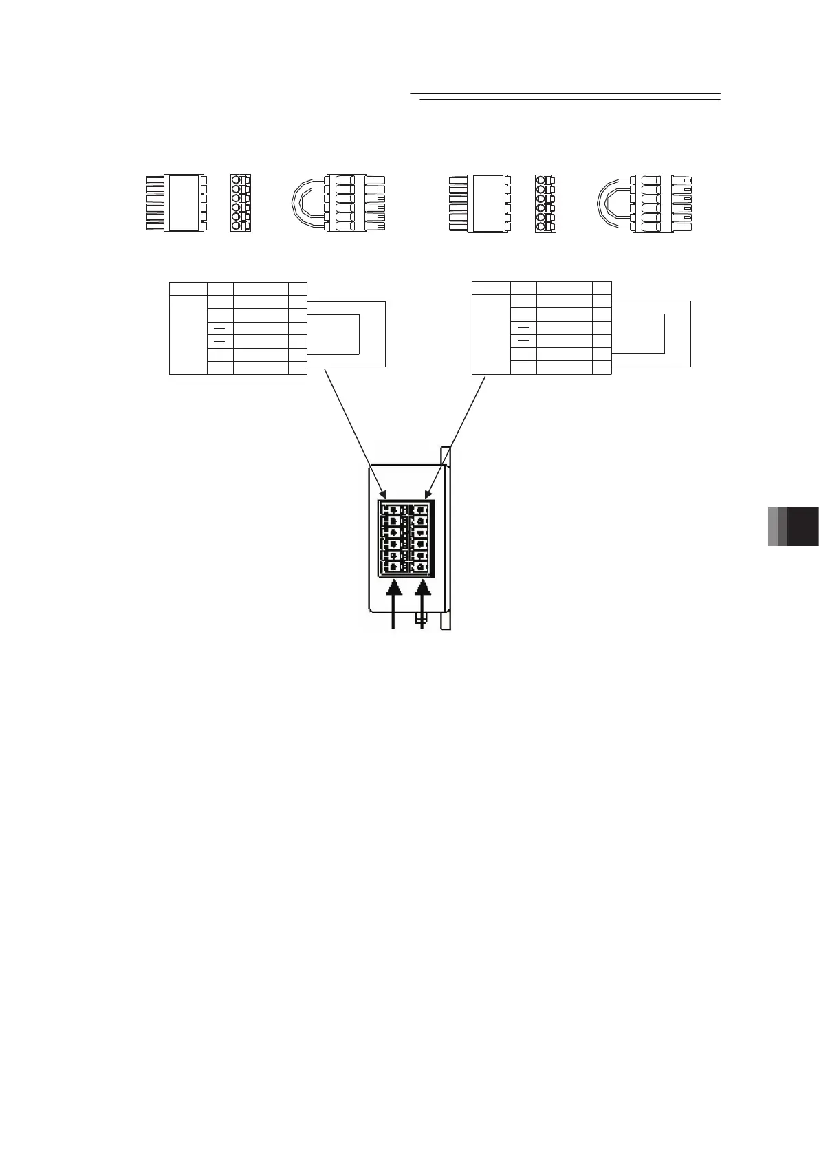
● Upper side (EMG) connector ● Lower side (ENB) connector
EMG1-
EMG1+
EMG2-
EMG2+
EMGIN
EMGOUT
ENB1-
ENB1+
ENB2-
ENB2+
ENBIN
ENBOUT
EMG1-
EMG1+
EMG2-
EMG2+
EMGIN
EMGOUT
1
6
7
12
Wiring
Color
YW
1
2
3
4
5
6
YW
YW
YW
Signal
No.
AWG24
ENB1-
ENB1+
ENB2-
ENB2+
ENBIN
ENBOUT
Wiring
Color
YW
7
8
9
10
11
12
YW
YW
YW
Signal
No.
AWG24
Upper
side
Lower
side
TP Adapter Side View
(3) Connection of dummy plug of TP adapter
When operating the controller with AUTO Mode, make sure to connect the enclosed dummy
plug (DP-4S).
(4) Enable function*
If you are using the enable function, set it to Enable using the controller parameter.
Parameter No.42 Enable function
0 ··· Enable
1 ··· Disable [Default setting at shipment]
* Enable function : It is the function to monitor the status of the signal (safety switch, dead
man’s switch on teaching pendant, etc.) to permit the devices to operate.

 Loading...


