POWER CON
PCON-CB/LC
14
6) LED for Current/Alarm Monitoring
In the ordinary use, it shows the command current percentage and shows the alarm code
during an alarm being generated.
LED Operation status
STS3 (GN)
STS2 (GN)
STS1 (GN)
STS0 (GN)
Status Display
• During servo-off: it displays the current command current ratio
(proportional to the rated current).
{ : Illuminating × : OFF
STATUS
3 2 1 0
Command Current Ratio
ALM8 ALM4 ALM2 ALM1 Simple alarm code
× × × × 0.00% to 6.24%
× × ×
{
6.25% to 24.99%
× ×
{ {
25.00% to 49.99%
×
{ { {
50.00% to 74.99%
{ { { {
75.00% to 100.00% or more
• During alarm generation: it displays the simple alarm code.
[Refer to 3.2.3 [7] and 3.3.2 [10] Binary Output of Alarm Data Output]
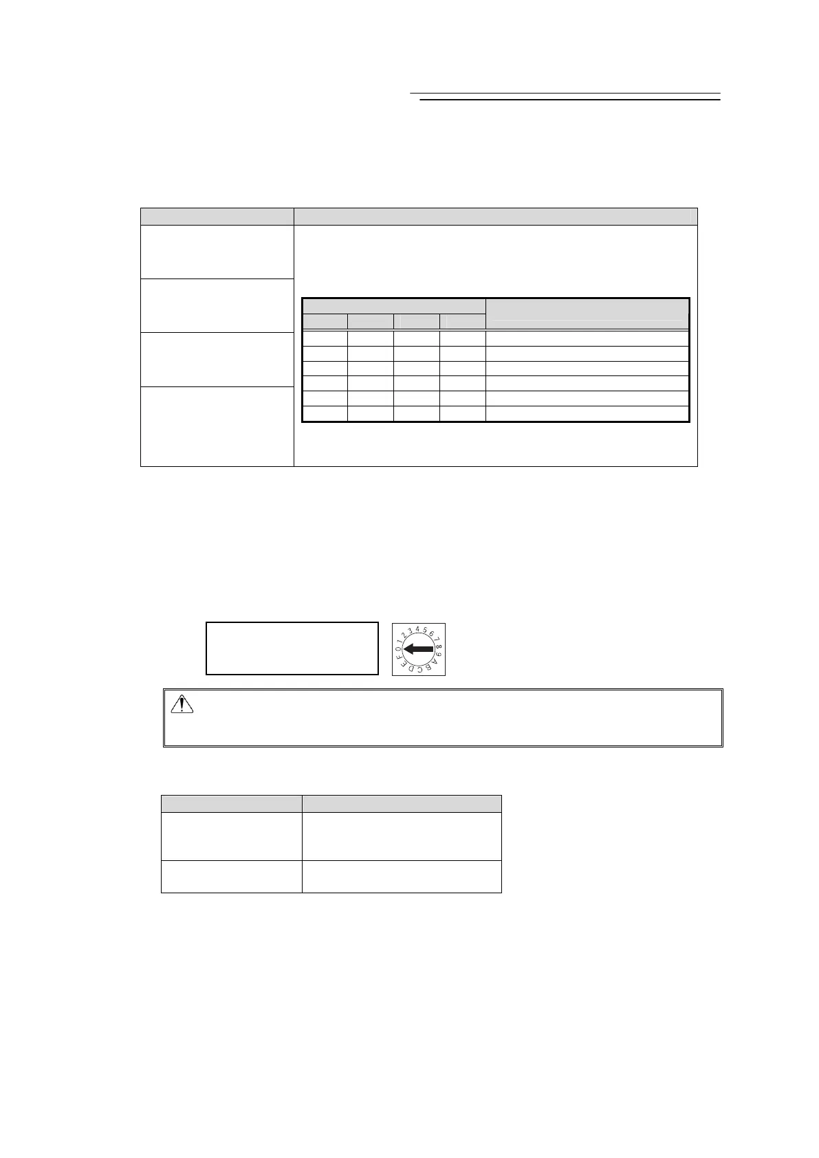
7) Axis Number Setting Switch
It is the switch to set the axis numbers when having an operation of multiple axes by the
serial communication, or when having the gateway operation.
Using the SIO converter allows multiple axes to be controlled on a teaching tool without
connection/disconnection of the connection cable connector. The SIO converter can specify
up to 16 axes with hexadecimal numbers 0 to F.
The setting of the switch is read at power-on of the controller. Changing the setting after the
power-on is invalid.
Caution : Note duplicate axis number setting, which causes a communication error
(alarm code 30C: no connection axis error) to occur and disables normal
communication.
8) Operation Mode Setting Switch (MANU/AUTO)
The switch for interlock.
Setting to switch
Operation status
AUTO
Allows auto operation by PIO
signals. The teaching tool can
only operate the monitor.
MANU
Allows the teaching tool to
operate the controller.
9) SIO Connector (SIO) [Refer to 2.3.5 SIO Connector Connection.]
The SIO connector is used to connect the controller with a teaching tool or a gateway unit
through a proper communication cable.
10) Motor • Encoder Connector [Refer to 2.1.3 [2] and 2.2.3 [2] Motor • Encoder Circuit]
It is the connector to connect the actuator motor and encoder cable.
Point the arrow at a desired
number with a flat-head
screwdriver

 Loading...


