Chapter 2 Wiring
POWER CON
PCON-CB/LC
46
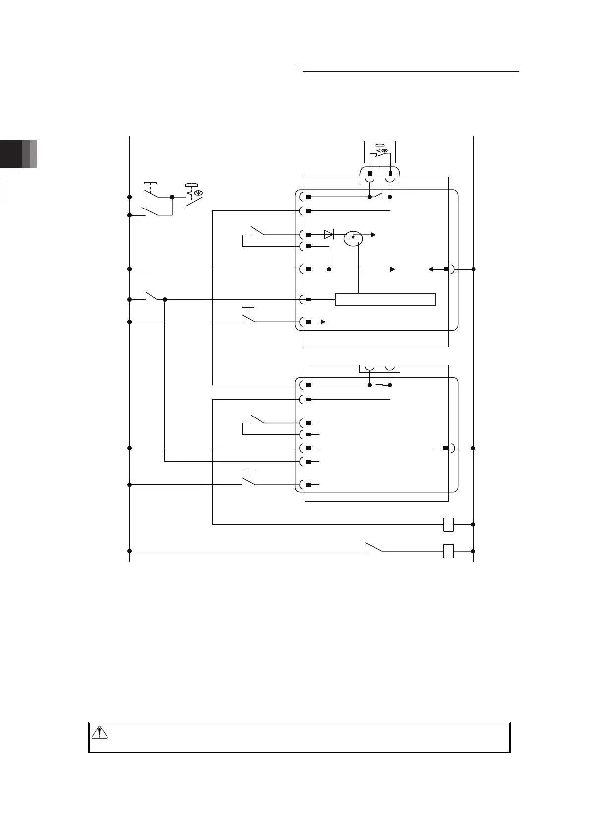
4) Refer to below when shutting the motor power off externally by the emergency stop input
when using two or more units of controllers.
24V 0V
0V
0V
Emergency
Stop Reset
Switch
Emergency
Stop Switch
CR1
CR1 CR2
S1
S2
MPI
MPO
24V
EMG-
BKLS
S1
S2
MPI
MPO
24V
EMG-
BKLS
CR1
(Note 3)
CR1
(Note 4)
Brake forced
release switch
Brake forced
release switch
Power Supply
Connector
PCON
Emergency-stop
Switch on the
Teaching Pendant
Control
power
supply
SIO Connector
(Note 1)
Power Supply
Connector
PCON
SIO Connector
(Note 1)
Motor power supply
CR2
(Note 2)
CR2
(Note 2)
Emergency Stop Control Circuit
Brake Release Power Supply
(Note) When connecting actuator equipped with brake
supply 24V power to forcibly release the brake.
Note 1 : The safety categories complied type (CGB Type, etc.) is not equipped with the relay to
have the controller automatically identify that a teaching tool was plugged in and switch the
wiring layout. Those other than the safety categories complied type do the automatic
identification and have S1 and S2 short-circuited.
Note 2 : When the motor driving source is cut off externally for a compliance with the safety
category, connect a contact such as a contactor to the wires between MPI and MPO. [Refer
to Chapter 10 Appendix]
Note 3 : The rating for the emergency stop signal (EMG-) to turn ON/OFF at contact CR1 is 24V DC
and 10mA or less.
Note 4 : For CR1, select the one with coil current 0.1A or less.
(Note) : When rebooting after shutting down, leave for 1sec or more.
(Note) : Do not attempt to supply only the motor power without supplying the control power.
Caution : If supplying power with using a 24V DC, having it turned ON/OFF, keep the 0V
connected and have the +24V supplied/disconnected (cut one side only).

 Loading...


