Chapter 2 Wiring
POWER CON
PCON-CB/LC
58
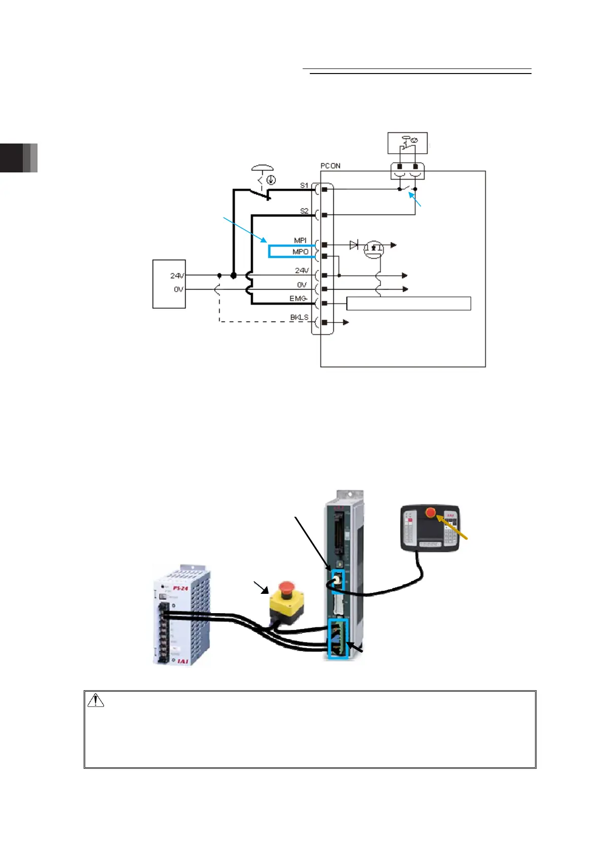
2) Example for wiring to operate actuator with the emergency stop input (EMG-) activated
The emergency stop gets released when +24V is supplied to EMG- Terminal on the controller,
and emergency stop activates if the power supply is shut, and stops the actuator operation,
turns the servo OFF and cuts off the motor power supply inside the controller.
Have an external emergency stop switch connected, and connect +24V to EMG- Terminal via
the emergency stop switch ON the teaching tool.
● Image of Wiring
Caution :x When supplying the power by turning ON/OFF the 24V DC, keep the 0V being
connected and have the +24V supplied/disconnected (cut one side only).
x The rating for the emergency stop signal (EMG-) is 24V DC and 10mA or less.
x Leave for 1 sec or more after shutting the power off before rebooting.
x Do not attempt to supply only the monitor power without supplying the control
power.
Wiring conducted at delivery
Drive Cutoff
Circuit
External Emergency
Stop Switch
Teaching Tool
Connection
Detection Circuit
(Contact opens
when connected)
PCON
Touch Panel Teaching, etc.
The emergency
stop switch is
activated.
SIO コネクタ
External Emergency
Stop Switch
(please prepare
separately)
Emergency Stop Switch
of Teaching Pendant
Power Supply Connector
SIO Connector
Control Power
Supply
Motor Power
Brake Release Power Supply
24V DC Power Supply
24V DC Power Supply
(please prepare
separately)
Power Supply Connector
SIO Connector
Emergency Stop Control Circuit
Note) Supply 24V when connecting
actuator equipped with brake
and release brake compulsorily

 Loading...


