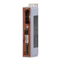
POWER CON
PCON-CB/LC
2.3 Wiring Method ............................................................................................................ 65
2.3.1 Wiring Layout of Power Supply Connector........................................................... 65
2.3.2 Connection to Actuator ......................................................................................... 66
2.3.3 Connection of PIO ................................................................................................67
2.3.4 Connection of Pulse Train Signal .........................................................................68
2.3.5 SIO Connector Connection................................................................................... 69
Chapter 3 Operation .....................................................................................................71
3.1 Basic Operation .......................................................................................................... 71
3.1.1 Basic Operation Methods ..................................................................................... 71
3.1.2 Parameter Settings ............................................................................................... 74
3.2 Operation in Positioner Mode..................................................................................... 75
[1] PIO Pattern Selection and Main Functions ......................................................... 75
[2] Overview of Major Functions............................................................................... 76
[3] Operation Modes of Rotary Actuator in Multiple Rotation Mode and
Command Limitations..........................................................................................76
3.2.1 Set of Position Table
(This section is not required in selection of pulse train control mode.) ................ 77
3.2.2 Control of Input Signal .......................................................................................... 82
3.2.3 Operation Ready and Auxiliary Signals = Common to Patterns 0 to 5................. 82
[1] Emergency Stop Status (EMGS)......................................................................... 82
[2] Operation Mode (RMOD, RMDS) ....................................................................... 83
[3] Servo ON (SON, SV, PEND)............................................................................... 84
[4] Home Return (HOME, HEND, PEND, MOVE).................................................... 85
[5] Zone Signal and Position Zone Signal (ZONE1, ZONE2, PZONE)....................89
[6] Alarm, Alarm Reset (*ALM, RES)........................................................................ 91
[7] Binary Output of Alarm Data Output (*ALM, PM1 to 8)....................................... 92
[8] Brake Release (BKRL)........................................................................................ 94
3.2.4 Operation with the Position No. Input = Operations of PIO Patterns 0 to 3............... 95
[1] Positioning [Basic]
(PC1 to PC**, CSTR, PM1 to PM**, PEND, MOVE, LOAD, TRQS)..................... 95
[2] Speed Change During the Movement............................................................... 100
[3] Pitch Feeding (Relative Movement = Incremental Feed).................................. 101
[4] Pressing Operation ........................................................................................... 103
[5] Tension Operation ............................................................................................. 108
[6] Multi-step Pressing............................................................................................ 110
[7] Teaching by PIO (MODE, MODES, PWRT, WEND, JISL, JOG+, JOG-)...........111
[8] Pause and Operation Interruption (*STP, RES, PEND, MOVE) ....................... 113
3.2.5 Direct Position Specification (Solenoid Valve Mode 1) = Operation of PIO
Pattern 4 ............................................................................................................. 115
[1] Positioning [Basic] (ST0 to ST6, PE0 to PE6, PEND) ...................................... 115
[2] Pitch Feeding (Relative Movement = Incremental Feed).................................. 117
[3] Pressing Operation ........................................................................................... 119
[4] Tension Operation ............................................................................................. 123
[5] Multi-step Pressing............................................................................................ 125
[6] Pause and Operation Interruption (ST*, *STP, RES, PE*, PEND)....................126
3.2.6 Direct Position Specification (Solenoid Valve Mode 2) = Operation of PIO
Pattern 5 ............................................................................................................. 128
[1] Home Return (ST0, HEND)............................................................................... 128
[2] Features of LS Signals (LS0 to 2)..................................................................... 132
[3] Positioning [Basic] (ST0 to ST2, LS0 to LS2) ................................................... 133
[4] Speed Change During the Movement............................................................... 135
[5] Pause and Operation Interruption (ST*, *STP, RES, PE*, PEND)....................137
3.3 Pulse Train Control Mode (for Pulse Train Type) ..................................................... 138
3.3.1 I/O Signal Controls.............................................................................................. 139

 Loading...