Quick Start Guide ~ RCON PROFINET IO Specification ~
p15
©2023 / IAI Corporation
STEP
3
STEP
1
STEP
2
Wiring
Table
of
Contents
4
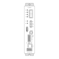
Wiring to System I/O Connector
In order to construct a stop circuit or enable input circuit, it is necessary to
perform wiring on the system I/O connectors.
Described below, shows how to wiring.
Insert the system I/O connector to the system I/O part on the gateway unit.
(1)
Perform wiring to each terminal of the system I/O connectors.
Here, shows an example of connecting a stop switch to a stop circuit. See the
example of connection below to have the wiring process.
(2)
RCON system
Keep the short-
circuit cables
(blue cables) as
shown in the
figure
(1) Prepare a cable with its diameter from
AWG 24 to 16.
(2) The stripped length
on a cable should be
10mm.
(3) While pressing the
orange extruded part
with a slotted
screwdriver, insert a
cable at the inlet and
put it till it hits the end.
Wiring method to system I/O connector
GoodBad
(4) Release the slotted screwdriver.
Stop Switch
★ (Optional)
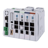
RCON Gateway Unit
(Model: RCON-GW-PRT)
RCON gateway unit /
System I/O connector
Items to prepare
System I/O Connector
(Model: DFMC1.5/5-ST-3.5)
Do not attempt to take off the cable between Auto /
Manu- and Auto / Manu+.
Servo-on from PLC will be disabled.
Prepare contact only when switching Auto and Manu
on the host side.

 Loading...