Quick Start Guide ~ RCON PROFINET IO Specification ~
p14
©2023 / IAI Corporation
STEP
3
STEP
1
STEP
2
Wiring
Table
of
Contents
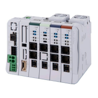
RCON gateway unit /
24V DC power supply
Items to prepare
In order to supply power to a controller, wiring should be performed on the
terminal on each connector.
See the example of connection below to have the wiring process.
RCON system
3
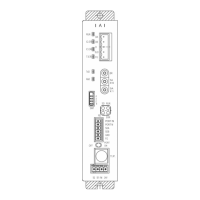
Wiring to the Power Supply Connector
RCON Gateway Unit
(Model: RCON-GW-PRT)
Wiring to RCON Gateway Unit
Frame Ground
*Annealed copper wire:
Connect with a ground wire of 1.6mm diameter
(2 mm
2
: AWG14) or higher.
Ground Terminal
Grounding resistance: 100 Ω or less
(Class D grounding construction)
24V DC Power Supply (Model: PSA-24(L))
(1) Refer to the following table for the wire
diameter for each connector.
(2) The strip length of
a cable should be:
・ MP:15mm
・ CP:10mm
・ FG:10mm
(3) Insert the wire all the
way into the terminal
port while pushing the
flathead screwdriver
into the hole next to
the wire insertion port.
Wiring method to power supply connector
MP
CP
GoodBad
(4) Remove the flathead screwdriver.
0V+24V
Connector Name
Compatible wire diameter
AWG (UL) (SQ(JIS))
MP
(Motor power supply)
AWG
20 to 8 (0.5 to 8 SQ)
CP
(Control power supply)
AWG
24 to 12 (0.2 to 3.5 SQ)
For the cables for MP (motor power supply) and CP (control power supply),
use a cable with thickness capable of current at the power supply part
(connector) of a controller.
Also, use cables with their rated temperature on the isolation sheath at 60°C
or higher.
CP
The current consumption of a controller should differ depending on the
connected actuator model code or driver unit.
Refer to [“Specification Edition Chapter 2 2.3 Specifications / Current Amperage”
in RCON Instruction Manual (ME0384)] for details.

 Loading...