14
Part 1 Installation
[7] Panel unit connector: This connector is used to connect the optional panel unit.
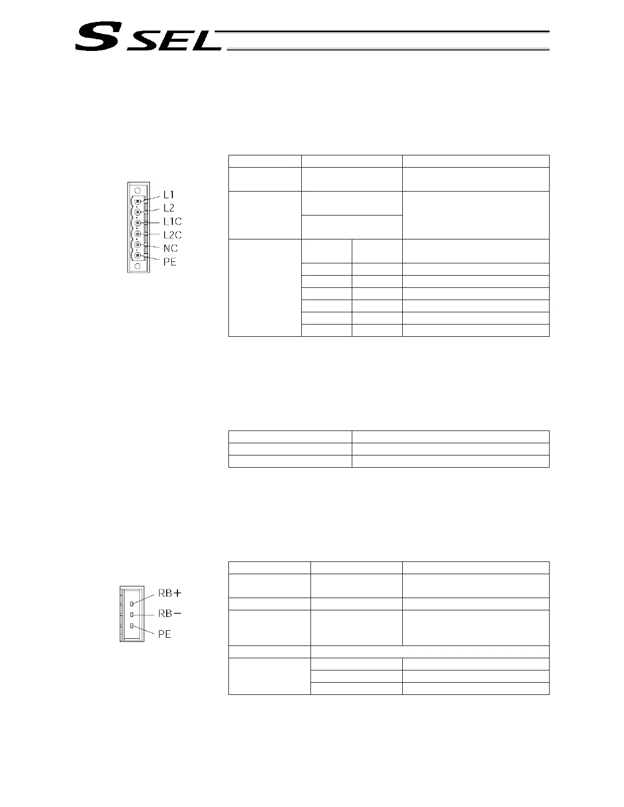
[8] Power connector: This connector is used to connect the 100/200-VAC single-phase input
power. The connector is divided into the control power input side and
the motor power input side.
Item Specification Remarks
Applicable
connector
6-pin, 2-piece
connector
MSTB2.5/6-STF-5.0 by
Phoenix Contact
Control power 0.75
mm
2
(AWG18) Applicable
cable size
Motor power 2 mm
2
(AWG14)
Recommended stripped-wire
length: 7 mm
Pin No.
Signal
name
1 L1 Motor power AC input
2 L2 Motor power AC input
3 L1C Control power AC input
4 L2C Control power AC input
5 NC Not connected
Terminal
assignments
6 PE Grounding terminal
The signal names are indicated on the mating connector.
[9] Grounding screw: This screw is used for protective grounding. It is connected inside the
controller to the PE of the power connector. Use this terminal if
protective grounding cannot be made with the two-piece connector in
order to comply with the safety standards, etc.
Item Description
Cable size 2.0 to 5.5 mm
2
or larger
Grounding method Class D grounding
[10] Regenerative unit connector: This connector is used to connect a regenerative resistance unit when
the built-in regenerative resistor does not provide sufficient capacity in
high-acceleration/high-load operation, etc. Whether or not one or more
external regenerative resistance units will be required depends on the
conditions of the specific application such as the axis configuration.
Item Specification Remarks
Applicable
connector
3-pin, 2-piece
connector
1-178128-3 (by AMP)
Connector name RB
Applicable cable
size
1.0 mm
2
(AWG17
or equivalent)
The cable comes with the
external regenerative
resistance unit.
Connected unit External regenerative resistance unit
RB+ Regenerative resistance +
RB- Regenerative resistance –
Terminal symbol
PE Grounding terminal

 Loading...


