25
Part 1 Installation Chapter 4 Name and Function of Each Part.
Part 1 Installation
(11) Panel window
This window consists of a 4-digit, 7-segment LED display and five LED
lamps that indicate the status of the equipment.
For the information shown on the display, refer to 2, “Explanation of
Codes Displayed on the Panel Window” or the “Error Code Table.”
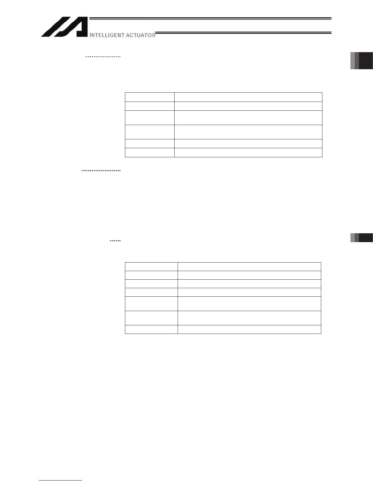
Meanings of Five LEDs
Name Status when the LED is lit
RDY CPU ready (program can be run)
ALM
CPU alarm (system-down level error), CPU hardware
error
EMG
Emergency stop has been actuated, CPU hardware
error, power-system hardware error
PSE Power-system hardware error
CLK System clock error
(12) Mode switch
This alternate switch with lock is used to command a controller operation
mode. To operate the switch, pull it toward you and tilt.
Tilting the switch upward will select MANU (manual mode), while tilting it
downward will select AUTO (auto mode). Teaching can be performed only
in the MANU mode, but auto program start is not enabled in the MANU
mode.
* With Q/QCT type controllers, connect the supplied dummy plug to the
teaching connector (9) while this switch is set to the AUTO mode.
(13) Standard I/O connector
This connector consists of a 50-pin flat connector and comprises 32-
input/16-output DIOs.
Overview of Standard I/O Interface Specifications
noitpircseDmetI
Connector name I/O
Connector Flat connector, 50-pin
Power supply Supplied from connector pin Nos. 1 and 50
Input
32 points (including general-purpose and dedicated
inputs)
Output
16 points (including general-purpose and dedicated
outputs)
Connected to External PLC, sensor, etc.

 Loading...


