24
Part 1 InstallationChapter 4 Name and Function of Each Part.
Part 1 Installation
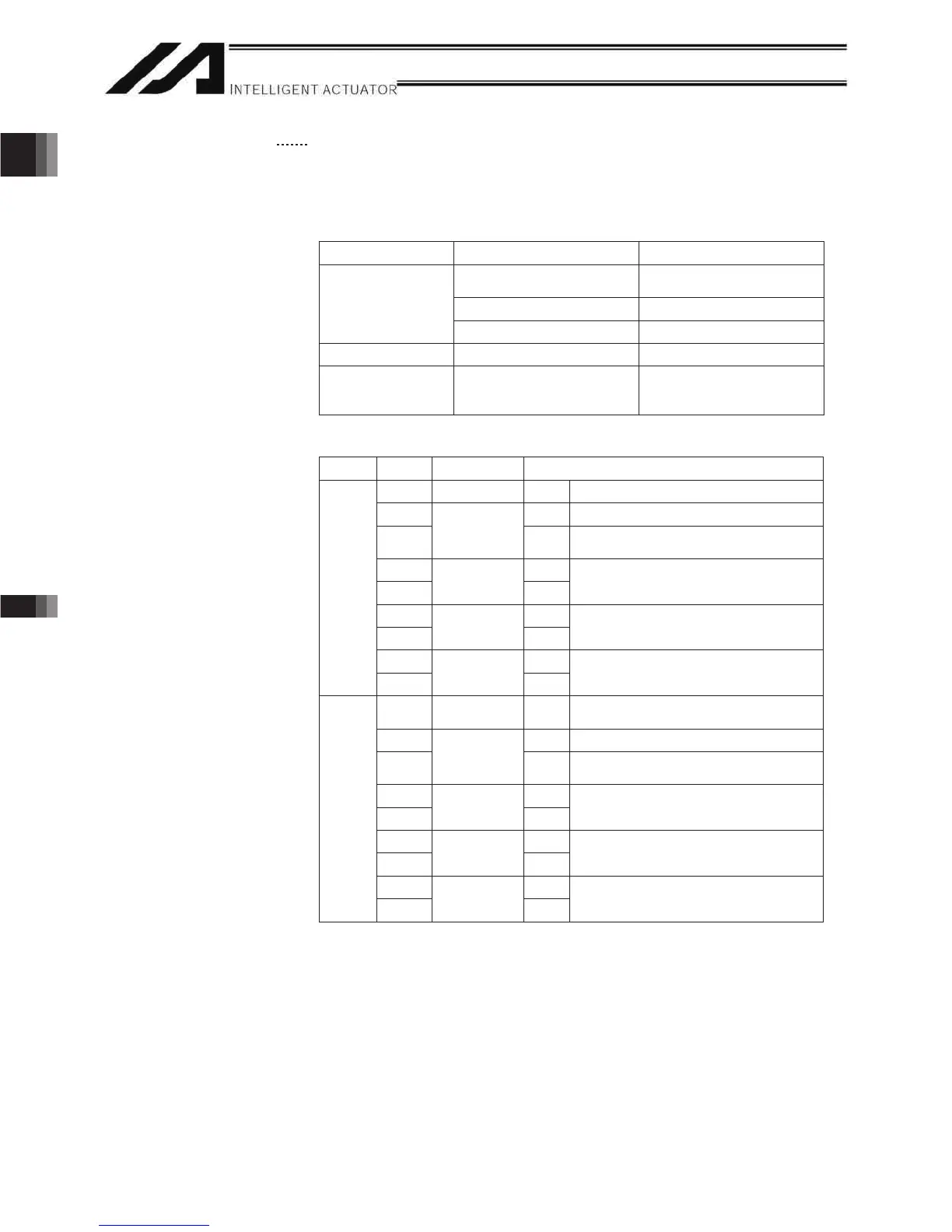
(10) System I/O connector
This I/O connector is used to control the safety actions of the controller.
With the global specification, a safety circuit conforming to a desired
safety category of up to level 4 can be configured using this connector
and an external safety circuit.
System I/O Connector Specifications
Item Overview Details
2-piece COMBICON
connector (18 pins)
MCD1.5/9-G1-3.5P26THR
(by Phoenix Contact)
Cable-end connector FMC1.5/9-ST-3.5
Connector
Applicable wire size AWG24 to 16
Connector name SYSTEM IO
Connected unit External safety circuit Emergency stop, safety
gate, ready out, external
relay cutoff
Overview of Terminal Assignments
Pin No. Signal name Description
9
DET IN
External contact error input
8
IN
Emergency-stop detection input
7
EMGin
+24V
24-V power output for emergency-stop
detection input
6
line+ Emergency-stop switch 1
5
EMG1
line- 8 mA (P/PCT type)
4
line+ Emergency-stop switch 2
3
EMG2
line- 8 mA (P/PCT type)
2
Out+
External relay drive cutoff contact output
Left
1
SDN
Out-
18 DET +24V
24-V power output for external contact
error input
17 IN Enable detection input
16
ENBin
+24V
24-V power output for enable detection
input
15 line+ Enable switch (safety gate, etc.)
14
ENB1
line- 8 mA (P/PCT type)
13 line+ Safety gate switch 2
12
ENB2
line- 8 mA (P/PCT type)
11 Out+ Ready signal contact output
Right
10
RDY
Out-
Only a terminal block is supplied without cable (EMG and ENB are shorted by
a cable). Do not supply power other than from a 24-VDC power supply to the
RDY and SDN contacts.

 Loading...


