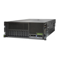
12. Perform the following:
a. Power off the system.
b. Display the selected IPL mode on the system unit control panel.
Function/Data Description
01______ Useincrement or decrement button and scroll to function 01.
01___A__ PressENTER to enter function 01 Selected IPL Type display.
Valid types, which appear in the sixth character position of the
Function/Data display, are A, B.
Is the selected mode the same mode the customer was using when the
power-on failure occurred?
No Go to step 13 of this procedure.
Yes Go to step 14 of this procedure.
13. Perform the following:
a. Power off the system.
b. Select the mode on the system unit operator panel the customer was using
when the power-on failure occurred.
c. Attempt to power on the system.
Does the system power on?
No Exchange the system unit operator panel card (see “System Rack
Removal and Replacement Procedures” on page 493).
This ends the procedure. Go to ″Map 0410: Repair Checkout″ in the
Diagnostic Information for Multiple Bus Systems.
Yes Go to step 14 of this procedure.
14. Is an eight-digit error code displayed on the system rack operator panel?
No Go to step 15 of this procedure.
Yes Go to “Entry MAP” on page 79.
15. Is the Power-on LED (on the operator panel) on continuously?
Note: The Power-on LED blinks during a normal power-on sequence. It should not
blink for more than 1 minute.
No Go to step 16 of this procedure.
Yes Go to step 17 of this procedure.
Chapter 3. Maintenance Analysis Procedures 93
 Loading...


