v No more than five expansion enclosures can be chained to port 1 (below the
control enclosure). The connecting sequence from port 1 of the node canister is
called chain 1.
v No more than four expansion enclosures can be chained to port 2 (above the
control enclosure). The connecting sequence from port 2 of the node canister is
called chain 2.
v No cable can be connected between a port on an upper canister and a port on a
lower canister.
v Attach cables serially between enclosures; do not skip an enclosure.
v The last enclosure in a chain must not have cables in port 2 of canister 1 and
port 2 of canister 2.
v Ensure that cables are installed in a tidy manner to reduce the risk of cable
damage when Storwize V7000 Unified replaceable units are removed or inserted.
v Arrange your cables to provide access to:
– The USB ports. Access is required to this port when you use the USB flash
drive to configure the system.
– The enclosures themselves. Access is required to the hardware for servicing
and for safely removing and replacing components using two or more people.
v Ensure that each SAS cable is fully inserted. A click is heard when the cable is
successfully inserted.
Note: If you make a mistake during cabling and must unplug a SAS cable, pull
the blue tag to release the cable.
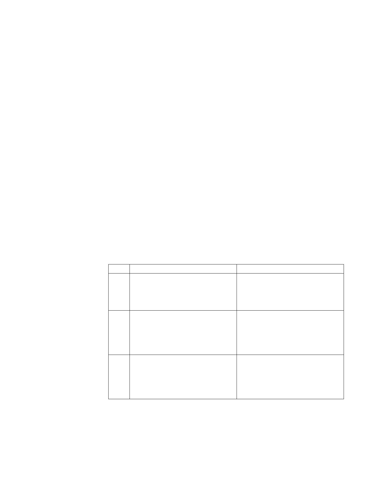
The following table refers to Figure 33 on page 44.
Table 13. Use this table to identify the file module, control enclosure, and expansion unit
port locations. Follow the links to identify detailed port locations.
Key Description
A Control enclosure. This unit consists of
two canisters; the upper and the lower.
The lower canister is position upside
down. See Figure 3 on page 4 for
detailed port locations.
1 SAS port 1
2 SAS port 23 SAS port 1
4 SAS port 2
B Expansion enclosure. This configuration
is for enclosure units 1, 3, 5. This unit
consists of two canisters; the upper and
the lower. The lower canister is position
upside down. See Figure 6 on page 6 for
detailed port locations.
Note: All port locations are identical for
B through C5 SAS port 1
6 SAS port 2
The lower unit is upside down:
7 SAS port 2
8 SAS port 1
C Expansion enclosure. This configuration
is for enclosure units 2, 4, 6. This unit
consists of two canisters; the upper and
the lower. The lower canister is position
upside down. See Figure 6 on page 6 for
detailed port locations.
Ports are identical to B.
Chapter 2. Performing the hardware installation 43

 Loading...


