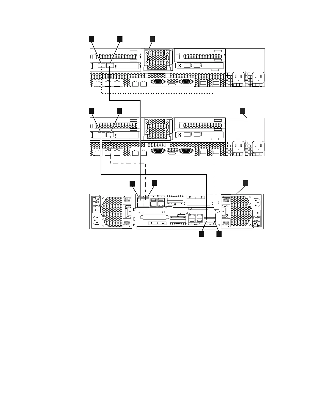
v A File module 1
v B File module 2
v C Storwize V7000 control enclosure
v 1 File module1 - Fibre Channel port 1
v 2 File module 1 - Fibre Channel port 2
v 3 File module 2 - Fibre Channel port 1
v 4 File module 2 - Fibre Channel port 2
v 5 Upper node canister - Fibre Channel port 1
v 6 Upper node canister - Fibre Channel port 2
v 7 Lower node canister - Fibre Channel port 2
v 8 Lower node canister - Fibre Channel port 1
2=3=4=5=6=7=8=
Note: If you want this control enclosure to communicate with other Storwize
V7000 control enclosures, storage controllers, the Storwize V7000 Unified or block
if s 0 00 3 3
3
4
PCI
3
4
PCI
2
1
3
4
5
6
7 8
CAUT IO N
CAUT IO NCAUT IO N
CAUT IO N
Disconnect all
supply power for
complete isolation
Disconnect all
supply power for
complete isolation
Disconnect all
supply power for
complete isolation
Disconnect all
supply power for
complete isolation
C
B
A
Figure 40. Diagram showing how to connect the file modules to the control enclosure using
Fibre Channel cables. Refer to previous table.
Chapter 2. Performing the hardware installation 53
|
|
|
|
|
|
|
|
|
|
|

 Loading...


