Powering on an expansion enclosure:
1. Power on the newly installed enclosures. Use the power switch on each of the
two power supply units in the back of the expansion enclosure.
2. Use the information in Table 18 on page 58 to verify the state of the light
emitting diodes (LEDs) on the system. Verify that no faults are detected. See the
Storwize V7000 Unified Problem Determination Guide PDF on the CD if problems
are encountered.
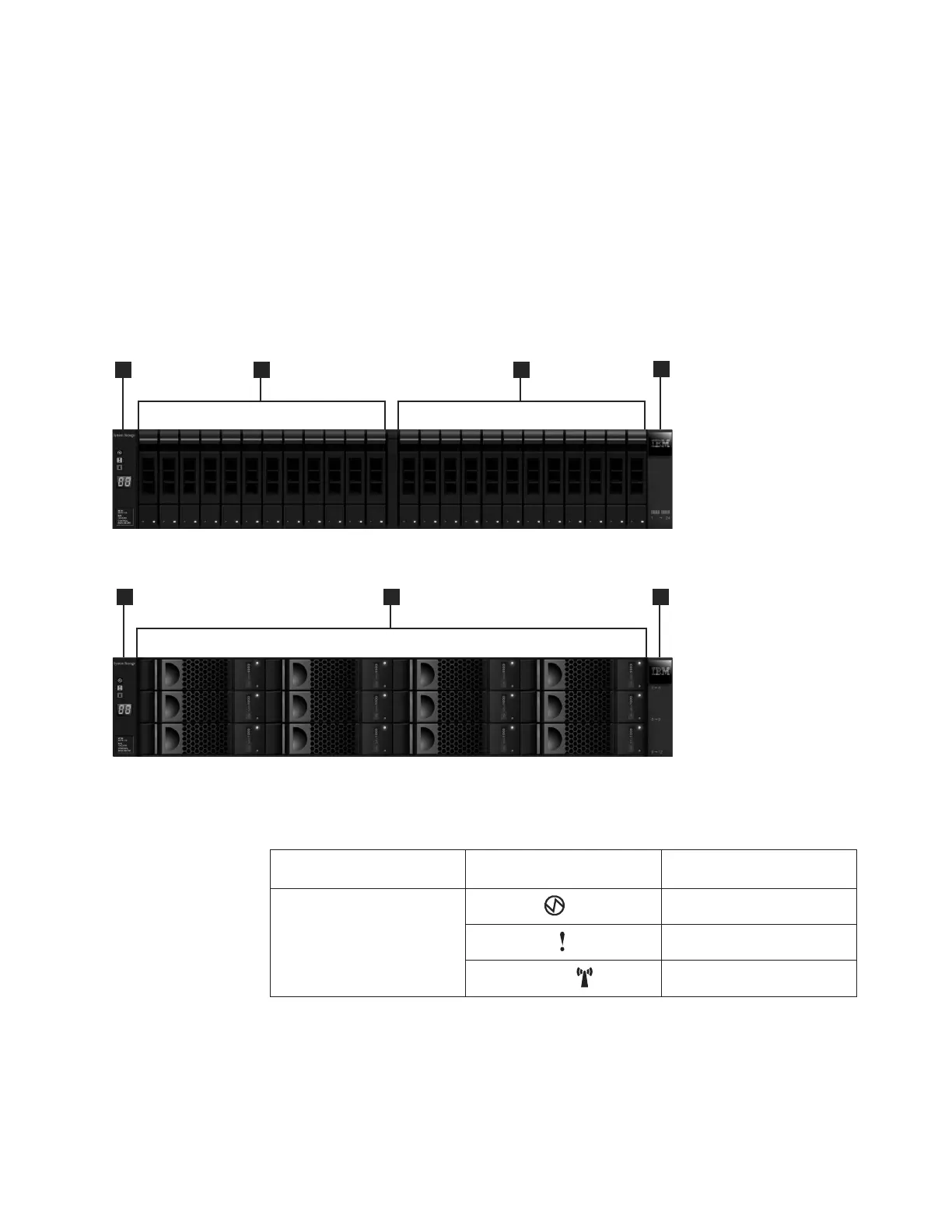
Both Figure 43 and Figure 44 show the location of the LEDs on the power supply
units, located at the front of the expansion enclosure. Figure 45 on page 58 shows
the location of the LEDs on the power supply units, located at the rear of the
expansion enclosure. The LEDs are located at position 1.
Table 17. LED status front of control enclosure or expansion enclosure. Refers to item [1] in
the figures above.
Hardware component LED name and symbol
If power on and no fault is
detected
Left enclosure end cap, front
of enclosure
Power, top
LED is on.
Fault, middle
LED is off.
Identify, bottom
LED is off.
svc00693
1 2 2
3
Figure 43. 24 drives and two end caps
svc00694
1
2
3
Figure 44. 12 drives and two end caps
Chapter 2. Performing the hardware installation 57

 Loading...


