2. Turn off the server and peripheral devices and disconnect the power cords and
all external cables.
3. Remove the cover (see “Removing the cover” on page 174).
4. Remove the bezel (see “Removing the bezel” on page 227).
5. Slide the hot-swap hard disk drive cage forward into the server until the screw
holes on the drive cage align with the screw holes on the chassis.
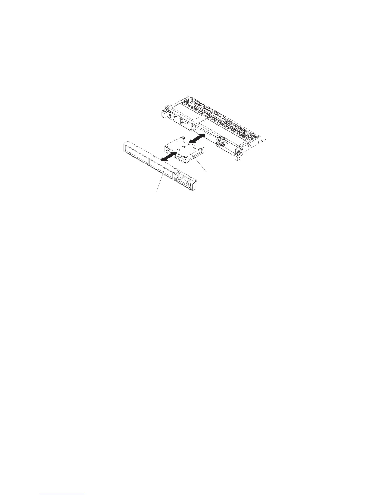
Bezel
Hard disk drive cage
6. Install the bezel (see “Installing the bezel” on page 227).
7. Install the hot-swap hard disk drive backplane (see “Installing the hot-swap
SAS/SATA hard disk drive backplane” on page 237).
8. Install the cover (see “Installing the cover” on page 174).
9. Reinstall the hard disk drives and filler panels.
10. Reconnect the power cords and any cables that you removed.
11. Slide the server into the rack.
12. Turn on the peripheral devices and the server.
Removing a PCI riser-card assembly
Note: A PCI riser-card assembly must be installed in slot 2 even if you do not
install an adapter.
To remove a PCI riser-card assembly, complete the following steps:
1. Read the safety information that begins on page vii and the “Installation
guidelines” on page 167.
2. Turn off the server and peripheral devices and disconnect the power cords and
all external cables.
Note: When you disconnect the power source from the server, you lose the
ability to view the LEDs because the LEDs are not lit when the power source is
removed. Before you disconnect the power source, make a note of which LEDs
are lit, including the LEDs that are lit on the operation information panel, on the
light path diagnostics panel, and LEDs inside the server on the system board;
then, see “Light path diagnostics LEDs” on page 104 for information on how to
solve the problem.
3. Remove the cover (see “Removing the cover” on page 174).
4. If an adapter is installed in the PCI riser-card assembly, disconnect any cables
that are connected to the adapter.
5. Grasp the rear of the PCI riser-card assembly from the rear and lift it out of the
PCI riser-card slot on the system board.
Chapter 5. Removing and replacing server components 233

 Loading...


