Installing a PCI riser-card assembly
Note: A PCI riser-card assembly must be installed in slot 2 even if you do not
install an adapter.
To install a PCI riser-card assembly, complete the following steps:
1. Read the safety information that begins on page vii and the “Installation
guidelines” on page 167.
2. Turn off the server and peripheral devices and disconnect the power cords and
all external cables.
3. Remove the cover (see “Removing the cover” on page 174).
4. Install the adapter in the new PCI riser-card assembly (see “Installing an
adapter” on page 180).
5. Set any jumpers or switches on the adapter as directed by the adapter
manufacturer.
6. If you are installing the PCI riser-card assembly on PCI slot connector 1 on the
system board, remove the PCI filler panel from the rear of the server.
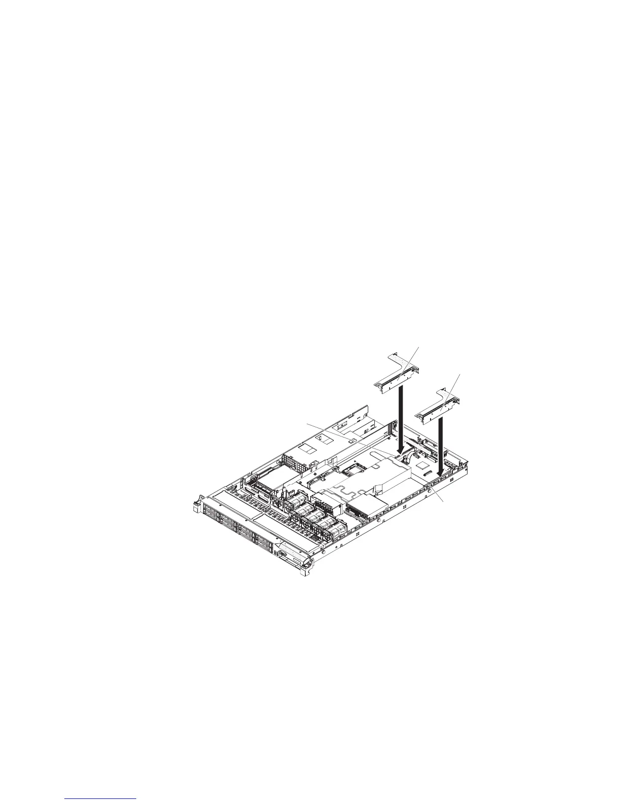
7. Align the PCI riser-card assembly with the PCI slot connector on the system
board; then, press down firmly until the PCI riser-card assembly is seated
correctly in the connector on the system board.
PCI riser
connector 1
PCI riser
connector 2
PCI riser-card assembly
(full-height, half-lenght adapters)
PCI riser-card assembly
(low-profile adapters)
Removing the PCI riser-card bracket from the riser card
To remove the PCI riser-card bracket from the riser card, complete the following
steps:
1. Read the safety information that begins on page vii and “Installation guidelines”
on page 167.
2. Turn off the server and peripheral devices and disconnect all power cords.
3. Remove the cover (see “Removing the cover” on page 174).
4. Remove the PCI riser-card assembly (see “Removing a PCI riser-card
assembly” on page 233).
5. Remove the screw that attaches the PCI riser card to the PCI bracket.
Chapter 5. Removing and replacing server components 235

 Loading...


