Server controls, LEDs, and power
This section describes the controls and light-emitting diodes (LEDs) and how to turn
the server on and off. For the location of the LEDs on the system board, see
“System-board LEDs” on page 21.
Front view
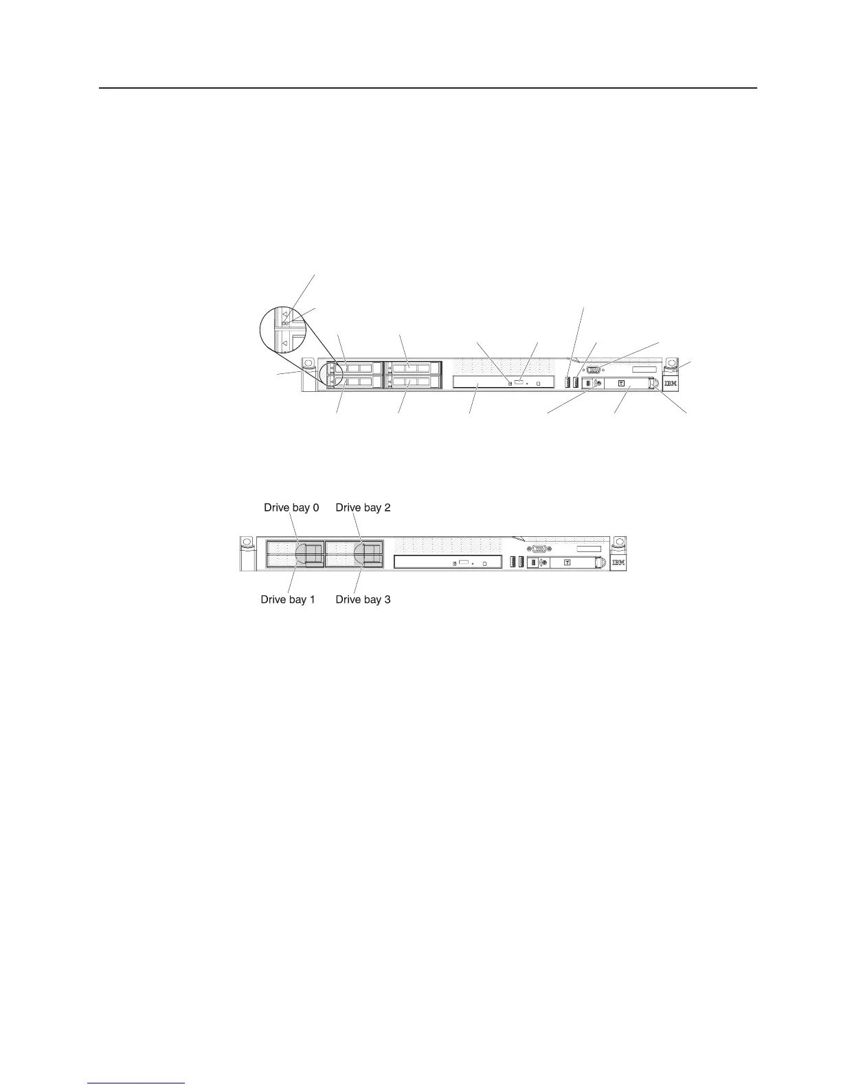
The following illustration shows the controls, LEDs, and connectors on the front of
the server.
Video
connector
USB 1
connector
Operator
information
panel
Drive bay 0 Drive bay 2
Drive bay 1 Drive bay 3
Rack
release
latch
Rack
release
latch
Hard disk drive
activity LED (green)
Hard disk drive
status LED (amber)
Optional
optical drive
eject button
Optional
optical drive
activity LED
Power-control
button and LED
Operator information
panel release latch
USB 2
connector
Optional
drive bay
The following illustration shows the front of the simple-swap server model.
v Rack release latches: Press the latches on each front side of the server to
remove the server from the rack.
v Hard disk drive activity LEDs: This LED is used on hot-swap SAS or SATA
hard disk drives. Each hot-swap hard disk drive has an activity LED, and when
this LED is flashing, it indicates that the drive is in use.
v Hard disk drive status LEDs: This LED is used on hot-swap SAS or SATA hard
disk drives. When this LED is lit, it indicates that the drive has failed. If an
optional IBM ServeRAID controller is installed in the server, when this LED is
flashing slowly (one flash per second), it indicates that the drive is being rebuilt.
When the LED is flashing rapidly (three flashes per second), it indicates that the
controller is identifying the drive.
v Optional DVD eject button: Press this button to release a DVD or CD from the
DVD drive.
v Optional DVD drive activity LED: When this LED is lit, it indicates that the DVD
drive is in use.
v Operator information panel: This panel contains controls and LEDs that provide
information about the status of the server.
v Operator information panel release latch: Slide the blue release latch to the
left to pull out the light path diagnostics panel and view the light path diagnostics
LEDs and buttons. See “Light path diagnostics panel” on page 11 for more
information about the light path diagnostics.
Chapter 2. Introduction 9

 Loading...


