v Remind button: This button places the system-error LED on the front panel into
Remind mode. In Remind mode, the system-error LED flashes every 2 seconds
until the problem is corrected, the system is restarted, or a new problem occurs.
By placing the system-error LED indicator in Remind mode, you acknowledge
that you are aware of the last failure but will not take immediate action to correct
the problem. The remind function is controlled by the IMM.
v NMI button: Press this button to force a nonmaskable interrupt to the
microprocessor. It allows you to blue screen the server and take a memory dump
(use this button only when directed by the IBM service support).
v Checkpoint code display: This display provides a checkpoint code that
indicates the point at which the system stopped during the boot block and POST.
A checkpoint code is either a byte or a word value that is produced by UEFI. The
display does not provide error codes or suggest components to be replaced.
v Reset button: Press this button to reset the server and run the power-on
self-test (POST). You might have to use a pen or the end of a straightened paper
clip to press the button. The Reset button is in the lower right-hand corner of the
light path diagnostics panel.
For additional information about the light path diagnostics panel LEDs, see “Light
path diagnostics LEDs” on page 104.
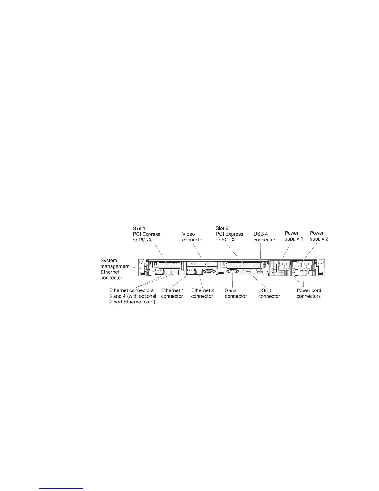
Rear view
The following illustration shows the connectors and LEDs on the rear of the server.
v PCI slot 1: Insert a low-profile PCI Express or PCI-X adapter into this slot. You
can purchase an optional PCI Express or PCI-X riser-card assembly with bracket
if you want to install a PCI adapter in this slot.
v PCI slot 2: Insert a half-length, full-height PCI Express or PCI-X adapter into this
slot. Standard models of the server come with one PCI Express riser-card
assembly installed in this slot. You can purchase an optional PCI-X riser-card
assembly with bracket if you want to install a PCI-X adapter in this slot.
v Power cord connector: Connect the power cord to this connector.
v Video connector: Connect a monitor to this connector. The video connectors on
the front and rear of the server can be used simultaneously.
Note: The maximum video resolution is 1600 x 1200 at 75 Hz.
v Serial connector: Connect a 9-pin serial device to this connector. The serial port
is shared with the integrated management module (IMM). The IMM can take
control of the shared serial port to perform text console redirection and to redirect
serial traffic, using Serial over LAN (SOL).
v USB connectors: Connect a USB device, such as a USB mouse or keyboard to
any of these connectors.
12 IBM System x3550 M3 Types 4254 and 7944: Problem Determination and Service Guide

 Loading...


