Rev AA Electrical Wiring Schematics 9-4
Electrical Wiring Schematics
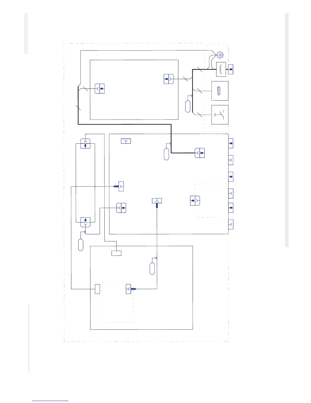
Figure 9-4 shows the electrical wiring schematic of the Clarity controller.
Figure 9-4: Electrical Wiring Schematic of the Clarity Controller
20-way FFC
402199
503300
CN1
Backlight
Inverter
703243
CN2
7
6
P2
13W Molex (0.156 inch)
5.7 inches CSTN Display/Touch-screen
702200
(Mounted below CLARiTY Board and Inverter)
X8
X9
X2
X13
X1
5W HDR 1.25 mm
X5
4-way FFC
RJ11-6pin
20-way FFC
503291
14W-HDR SIL 0.1 inch
8W-Molex MiniFit
Optional
Ethernet/RS-232
Board - 603305
CLARiTY Board
603105
USB (A)
9W-D
RJ45
25W-D
9W-D
9W-D
X11
X15 X16
X6
X3
X14
Memory
Stick
RS-232
Comm's
(Option)
Ethernet
(Option)
Printer
Data
Printer
Power
RS-232
Comm's
S1 FUI
P1
Mains Power
Switch (I/O)
Mains
Fuse
Mains
Inlet
T5AH250V
L1
PE
3
3
24
503299
P1
5W Molex (0.156 inch)
Universal Power Supply
702219
(Mounted above CLARiTY Board)
Hirschmann CA 3 GS
ICE Pegasus Service Manual