25
2. ADVANCED OPERATIONS
Operating PSK
A PSK encoder/decoder is built into the IC-7610. You
can connect a USB keyboard to the transceiver and
operate PSK without a PC.
If you would rather use your PSK software, refer to its
manual.
PSK DECODE screen (MENU1)
PSK DECODE screen (MENU2)
Function Action
<MENU1>
<MENU2>
Selects the Function menus.
HOLD/
CLR
Touch
Turns the Hold function ON or OFF.
• “
” is displayed and the
current screen freezes..
Touch
1 sec.
Clears the displayed characters.
AFC/NET
Touch
Toggles between (AFC:ON),
(AFC/NET: ON) or OFF.
Touch
1 sec.
Adds the offset frequency to the
operating frequency.
TX MEM Displays the PSK MEMORY screen.
ADJ Enters the threshold level adjustment mode.
DEF
Touch
1 sec
Sets the threshold levels to their defaults.
L This key is displayed after
touching [ADJ].
MAIN/
SUB
Toggles between the Main and Sub bands.
B/QPSK
Toggles between the BPSK and QPSK
modes.
31/63
Toggles between the BPSK31 and BPSK63
modes.
LOG
Displays the PSK DECODE LOG set screen.
•
type.
LOG
VIEW
Displays the PSK DECODE LOG VIEW
screen.
• You can view the saved log contents.
SET Displays the PSK DECODE SET screen.
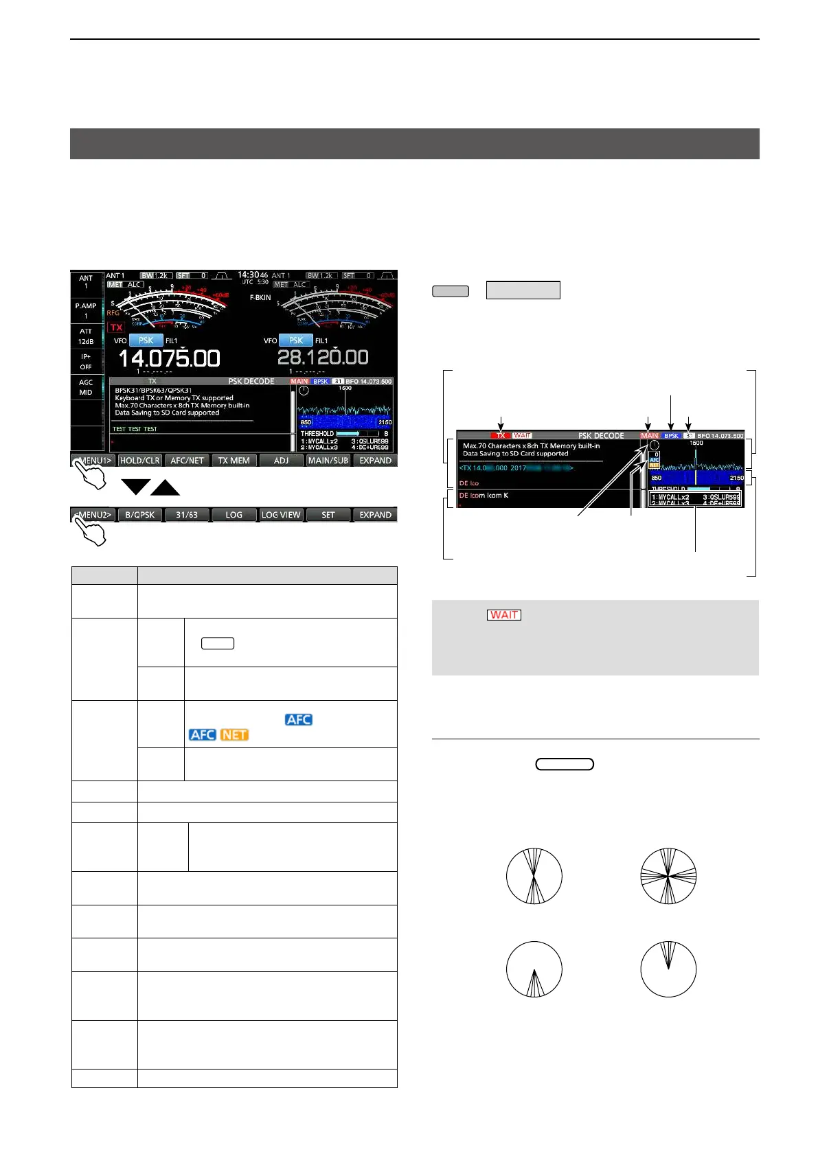
D Displaying the PSK DECODE screen
With the built-in demodulator and decoder, received
PSK signals are displayed on the PSK DECODE
screen.
L The decode screen for the PSK mode slightly
differs from that of the RTTY mode.
» DECODE
PSK DECODE screen
Decoded characters
Vector tuning
indicator
Transmitting
Waterfall display
PSK memory title
AFC/NET
FFT scope
Selected band (MAIN)
B/QPSK mode
BPSK 31/36
Transmitting contents
(Example: PT1)
Indication example
Tuned BPSK signal
BPSK/QPSK idle signal Unmodulated signal
Tuned QPSK signal
Vector tuning indicator
The Vector tuning indicator is displayed when tuning PSK
signals by rotating
.
NOTE: “ ” appears next to the transmitting
status indicator on the PSK DECODE screen while
buffering. If this appears, stop typing for a while and
try transmitting again.
 Loading...


