3
1. ADVANCED CONNECTIONS
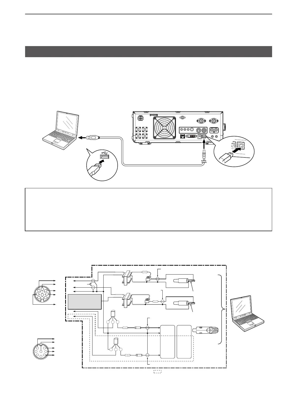
FSK, AFSK, PSK connections
The transceiver has a mode key for RTTY and PSK. You can use a PC and an application software to operate
RTTY and PSK using a USB cable. However, if you want to operate AFSK or other digital modes, you can use
the ACC socket on the rear panel through an interface unit. See the interface circuit diagram below for details.
(Icom does not guarantee performance of the application software, PC, network device or network settings.)
PC
Type A
Type B
To a USB port
To the USB port
A/B USB cable (user supplied)
When using the USB port
TIP:
• If you set the “USB Serial Function” item to “RTTY Decode,” the decoded RTTY signals are output from the
USB port.
• Download the USB driver and the installation guide from the Icom website.
http://www.icom.co.jp/world/index.html
(Support > Firmware Updates/Software Downloads > Transceiver)
When using the ACC socket or the microphone connector
CEB
RTS
GND
D-Sub 25
D-Sub 9
CEB
TXD
A
B
C
D
E
1
2
3
4
5
6
7
8
B
F
E
D
C
8
2
7
6
1
3
5
4
A
B
C
D
E
• Connecting to [ACC 1]
• Connecting to [MIC]
Shield cable
ACC: Connect to [C]
MIC: Connect to [F]
Shield cable
Shield cable
Shield cable
Shield cable
Connect to
LINE IN or
MIC IN
No connection
No connection
Connect to
SP OUT
Connect to
COM port
(Trimpot)
(Trimpot)
★1
Pin 4
Pin 7
Pin 7
Pin 5
Pin 2 Pin 3
★1
★2
★2
PC
(Rear panel)
(Front panel)
★1: NPN transistor
(2SC1815)
★2: Switching diode
(1S1588)
The sections shown in short dashes are required only when
Baudot RTTY is used in the FSK (RTTY) mode.
(Not required for other digital modes such as SSTV or PSK)
NOTE: You cannot
operate FSK RTTY when
you connect the circuit to
the microphone connector.
Interface circuit example for digital modes (User supplied)
LSee pages 13-2 to 13-3 in the Basic Manual for details on the ACC 1 socket and MIC connectors.
 Loading...


