What causes distorted transmitted signals on Icom IC-910H?
- Ccolleen73Sep 5, 2025
If transmitted signals from your Icom Transceiver are distorted, it's likely that the [MIC GAIN] is set too far clockwise. Adjust [MIC GAIN] to a suitable level.
What causes distorted transmitted signals on Icom IC-910H?
If transmitted signals from your Icom Transceiver are distorted, it's likely that the [MIC GAIN] is set too far clockwise. Adjust [MIC GAIN] to a suitable level.
How to start mode select scan on Icom Transceiver?
If the mode select scan does not start on your Icom Transceiver, first ensure that mode select scan mode has been selected by pushing [SPCH•LOCK] for 1 second on the desired operating mode programmed channel. Also, make sure that more than two channels are programmed with the desired operating mode; if not, program additional channels.
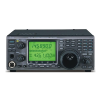
Why no announcement when SPCH is pushed on Icom IC-910H?
If there is no announcement when [SPCH] is pushed on your Icom Transceiver, first check if the optional voice synthesizer unit, UT-102, has been installed, and install it if it hasn't. If installed, ensure the announcement level is set to a suitable level in the SPCH set mode using [SET] and [SPCH]. Finally, verify that the announcement language is set to “Eng” (or JPn) in the SPCH set mode using [SET] and [SPCH], and change it if it's set to “oFF.”
Why no sound from my Icom IC-910H speaker?
If no sound is coming from the Icom Transceiver's speaker, first, ensure that the volume level isn't too low by rotating [AF] clockwise to a suitable listening level. Also, check if the squelch is closed and rotate [RF/SQL] to the 12 o’clock position to open it. Finally, verify that the transceiver is not in transmitting mode by pushing [TRANSMIT] to receive, or check the SEND line of an external unit.
Brand | Icom |
---|---|
Model | IC-910H |
Category | Transceiver |
Language | English |
Covers power, transmit, signal processing, audio, and RF power controls on the front panel.
Covers unpacking, grounding, location selection, and antenna connection.
Guides on connecting DC power supply and vehicle battery.
Covers initial settings after reset and the CPU reset procedure.
Explains MAIN/SUB bands, accessing SUB band, VFO operation, and band selection.
Details frequency setting, tuning steps, keypad entry, and mode selection.
Explains volume, squelch, RIT, IF shift, AGC, AFC, and FM center indicator.
Details FM, VOX, Repeater, SSB, Split, Duplex, and CW operations.
Covers tracking selection, satellite memory, preparation, loop tests, and operation procedures.
Details AFSK functions, connections, operating notes, and ACC socket settings.
Guides on installing UT-102, UT-106 DSP, UX-910, CR-293, and FL-132/FL-133.
Provides a chart for diagnosing and solving common problems.