© 2009 IDS Imaging Development Systems GmbH 189
9 Specifications
9.3 Electrical Specifications
9.3.1 USB uEye SE
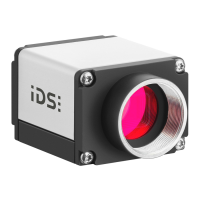
Pin Assignment
9-pin micro D-Sub socket
Figure 169: Pin assignment
of the micro D-Sub socket
USB power supply (VCC) 5 V
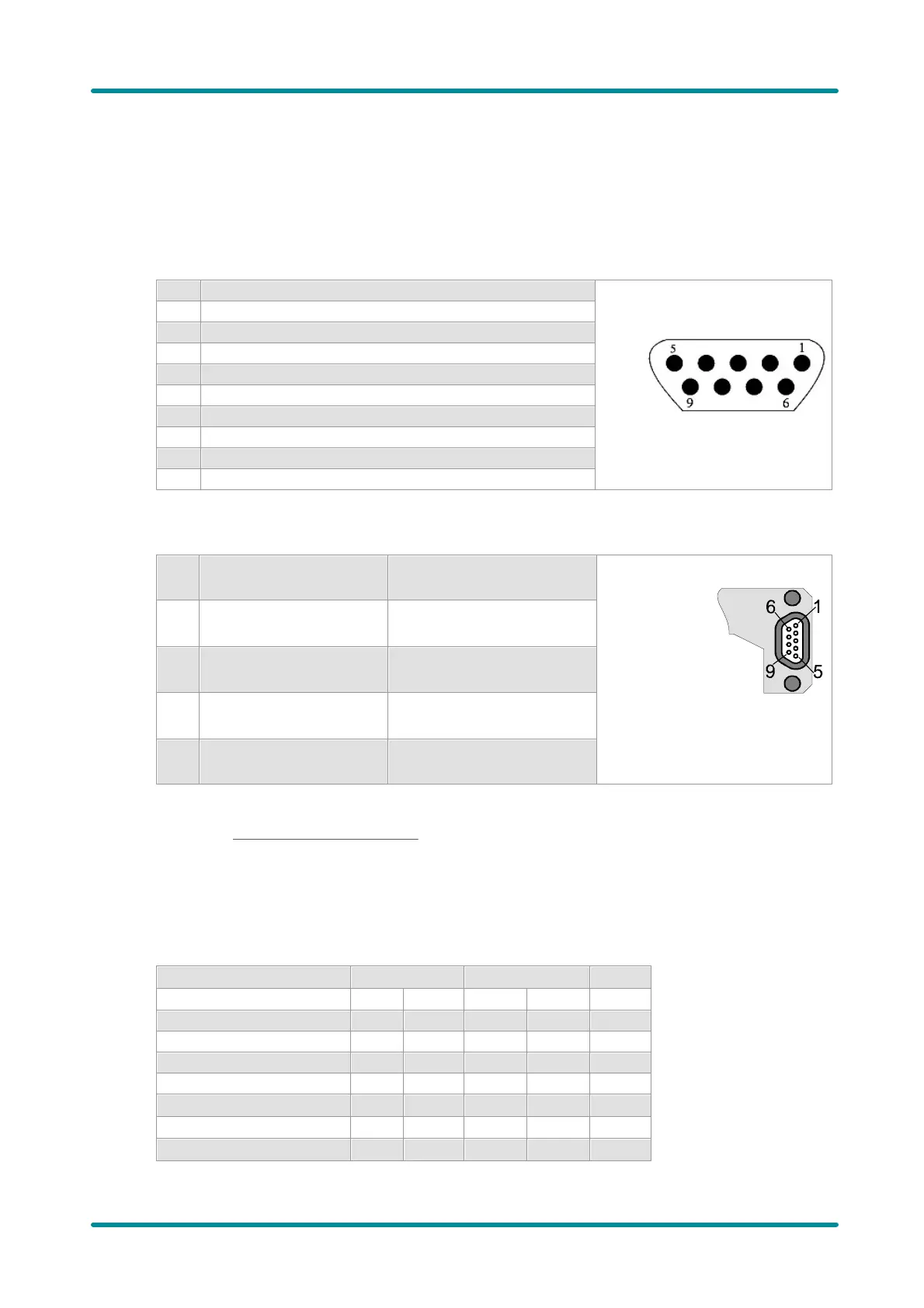
Pin assignment of the uEye special cable for USB 2.0, trigger and flash
Figure 170: Pin
assignment of the
trigger cable
(D-Sub)
For a comprehensive list of all cables and connectors available for USB uEye SE cameras, please
refer to the USB uEye SE Accessories section.
Digital Input Wiring (Trigger)
Digital input specifications
Trigger pulse width (edge)
 Loading...