EasyManuals Logo

IDS uEye series User Manual

IDS uEye series
226 pages
To Next Page IconTo Next Page
To Previous Page IconTo Previous Page
Page #193 background imageLoading...
Page #193 background image
© 2009 IDS Imaging Development Systems GmbH 193
9 Specifications
9.3.2 USB uEye RE
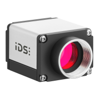
Pin Assignment of the USB Connector
5 pin Binder plug (USB connector)
Pin
Description
4
5
1
2
3
Figure 176: Pin
assignment of the
USB uEye RE USB
connector (Binder)
1
USB data (+)
2
USB ground (GND)
3
Shielding
4
USB power supply (VCC)
5
USB data (-)
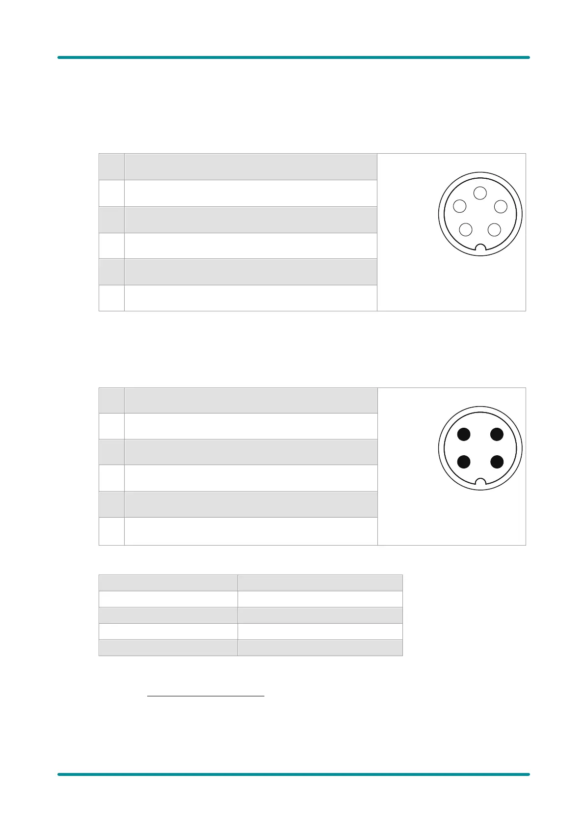
Pin Assignment of the I/O Connector
4 pin Binder socket (trigger connector)
Pin
Description
1
2
3
4
Figure 177: Pin
assignment of the
USB uEye RE trigger
connector (Binder)
1
Digital output (+)
2
Digital output (-)
3
Digital input (+)
4
Digital input (-)
Color coding for USB uEye RE trigger cable
Color
Assignment
white
Digital input (+)
brown
Digital input (-)
green
Digital output (-)
yellow
Digital output (+)
For a comprehensive list of all cables and connectors available for USB uEye RE cameras, please
refer to the USB uEye RE Accessories section.

Table of Contents

Questions and Answers:

Question and Answer IconNeed help?

Do you have a question about the IDS uEye series and is the answer not in the manual?

IDS uEye series Specifications

General IconGeneral
SensorCMOS
InterfaceUSB 2.0, USB 3.0, GigE
ShutterGlobal or Rolling Shutter
Power SupplyVia USB or external power (depending on model)
Operating SystemWindows, Linux
MountC-mount or CS-mount
Dimensions29 x 29 x 29 mm