© 2009 IDS Imaging Development Systems GmbH 205
9 Specifications
9.3.5 GigE uEye HE
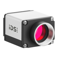
Pin Assignment of the GigE Connector (RJ45)
8-pin RJ45 socket
Figure 194: Pin
assignment of the
GigE uEye HE RJ45
socket (ST2)
The RJ45 socket of the GigE uEye HE complies with the IEC 60603-7 standard.
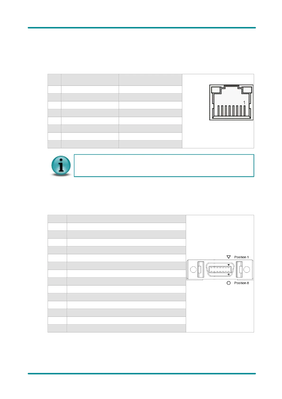
Pin Assignment of the I/O Connector
14-pin MDR 14 socket
Figure 195: Pin assignment of the
GigE uEye HE I/O socket (ST1)
General Purpose I/O 1 (not potential-free)
General Purpose I/O 2 (not potential-free)
RS232 RxD (not potential-free)
RS232 TxD (not potential-free)
 Loading...