© 2009 IDS Imaging Development Systems GmbH206
User Manual uEye Cameras V3.32
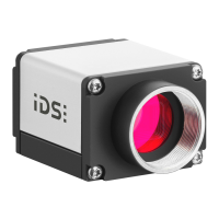
Pin assignment of the 12-wire connecting cable (14-pin MDR 14 plug)
Figure 196: Pin assignment of the
GigE uEye HE connecting cable
(12 wires)
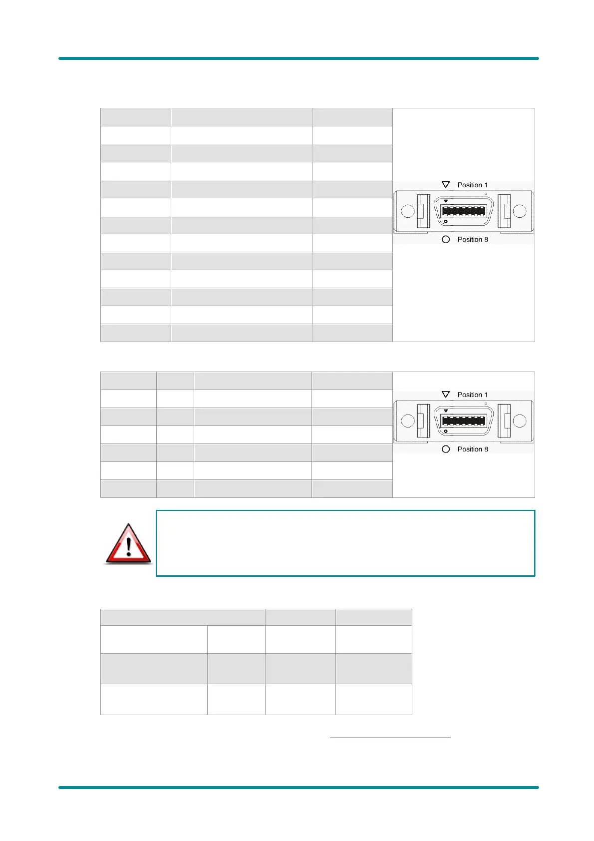
Pin assignment of the I/O and power cable without AC adapter
Figure 197: Pin assignment of the
GigE uEye HE I/O and power
cable (with/without AC adapter)
The power supply (VCC) must be connected to pins 2 and 9. In addition, the power supply
ground wire must be connected to all 4 GND pins (pins 1, 7, 8, and 14). If this is not
possible due to insufficient space, connect at least pins 1 and 8 to the power supply
ground wire.
For EMC reasons, the cable shield must not be connected to the GND wire.
Power supply
For information on the camera's connected load, see Specifications: Sensor Data chapter.
 Loading...