EasyManuals Logo

IDS uEye series User Manual

IDS uEye series
226 pages
To Next Page IconTo Next Page
To Previous Page IconTo Previous Page
Page #207 background imageLoading...
Page #207 background image
© 2009 IDS Imaging Development Systems GmbH 207
9 Specifications
To ensure a sufficient voltage (6...24 V) at the camera input, we recommend the following
AC adapter voltages:
Power cable length
AC adapter voltage
up to 5 m
5-10 m
10-20 m
20-30 m
30-50 m
9-24 V
12-24 V
15-24 V
18-24 V
24 V
The inrush current of the GigE uEye HE may temporarily increase to up to 2 A.
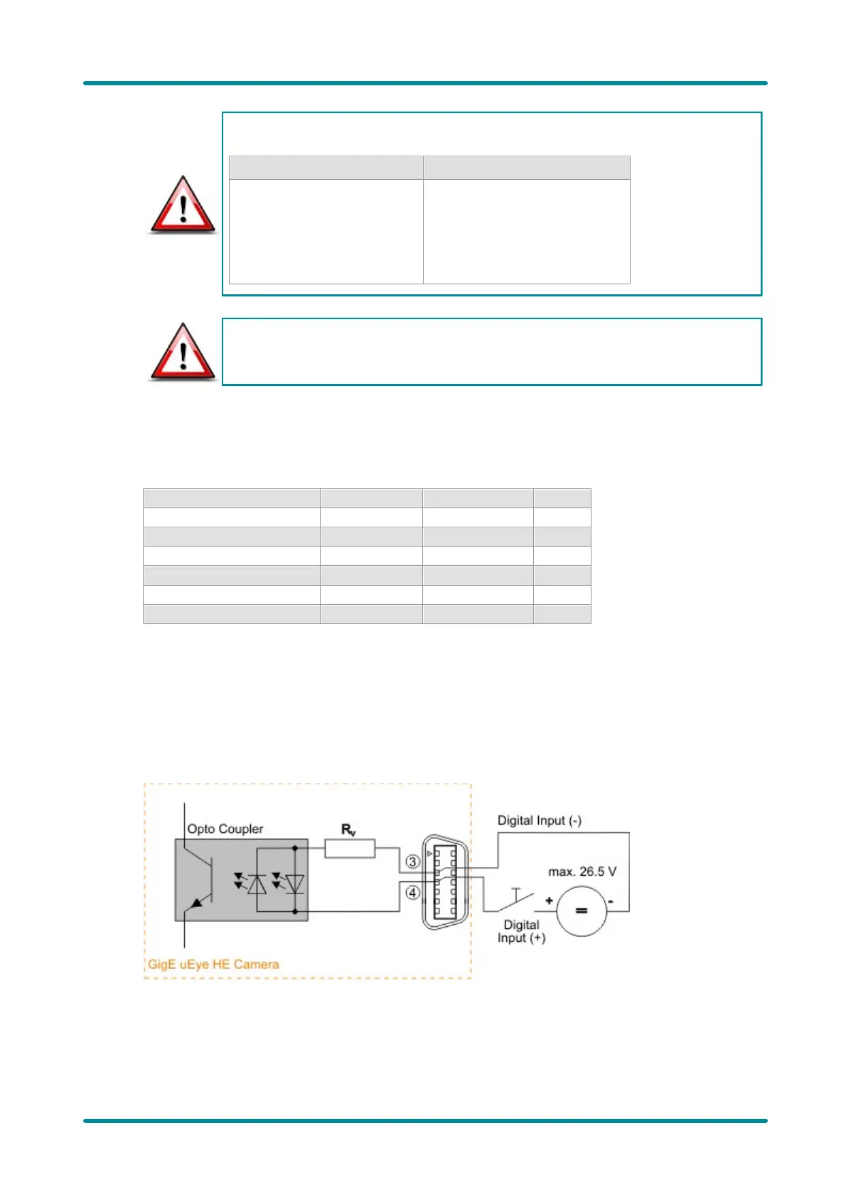
Digital Input Wiring (Trigger)
Digital input specifications
Min.
Max.
Level low
0
2
V
Level high
5
26,5
V
Trigger pulse width
1
-
µs
Trigger edge steepness
35
V/ms
Breakdown voltage
50
V
Input current
10
-
mA
For interpreting the trigger signal, either the positive or the negative edge can be used. The digital
input is galvanically isolated using an opto coupler to protect the camera and the PC against surges.
Only DC voltages may be applied to the digital input.
Digital input wiring
The following figures show examples of how the digital input is wired.

Table of Contents

Questions and Answers:

Question and Answer IconNeed help?

Do you have a question about the IDS uEye series and is the answer not in the manual?

IDS uEye series Specifications

General IconGeneral
SensorCMOS
InterfaceUSB 2.0, USB 3.0, GigE
ShutterGlobal or Rolling Shutter
Power SupplyVia USB or external power (depending on model)
Operating SystemWindows, Linux
MountC-mount or CS-mount
Dimensions29 x 29 x 29 mm