© 2009 IDS Imaging Development Systems GmbH208
User Manual uEye Cameras V3.32
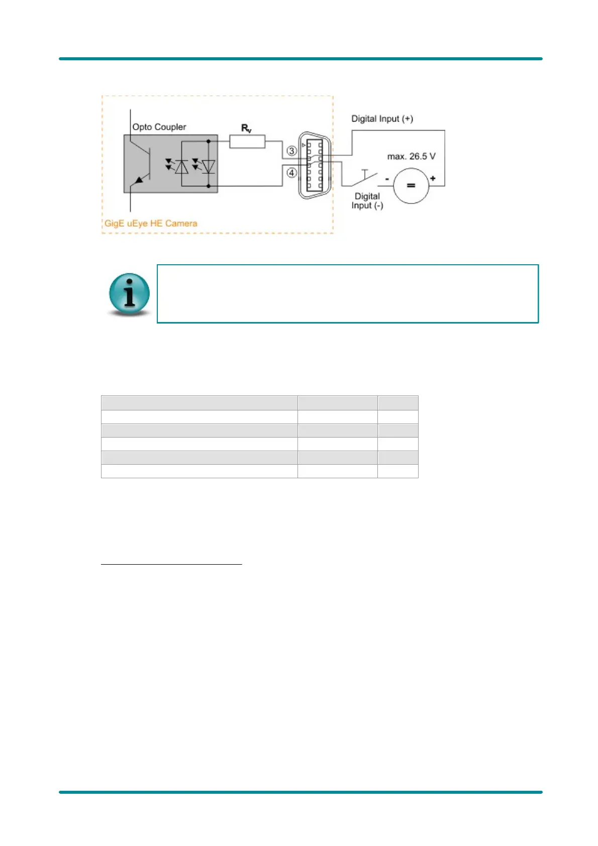
Figure 198: Trigger connector (schematic)
The opto isolated digital input has two LEDs which are not activated in parallel. This way,
you can use either positive or negative signals for triggering. The input polarity can be
selected as desired. The Trigger+ and Trigger- labeling in the figures above is only used
for schematic illustration.
Digital Output Wiring (Flash)
Digital output specifications
Output current (short-time)
Output current (permanent)
Collector power dissipation
The digital input is galvanically isolated using an opto coupler to protect the camera and the PC
against surges. Only DC voltages may be applied to the digital input.
The output of the opto coupler can be used as an open collector or open emitter output. This means
that the output signal can be connected to ground or to the supply voltage. The output signal is
active if the collector-emitter switch is closed (software setting: Flash high active, see also the
Camera Properties: Input/Output section).
 Loading...