© 2009 IDS Imaging Development Systems GmbH 209
9 Specifications
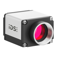
Digital output wiring
Figure 199: Flash connector (schematic)
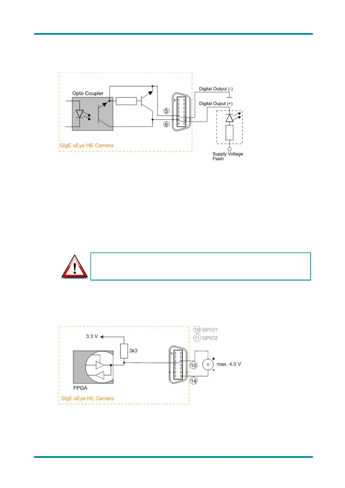
General Purpose I/O Wiring
GPIO specifications
The two GPIOs (General Purpose I/O) can be used as inputs or outputs. This selection is made by
software using the corresponding SDK API functions. Please observe the following criteria:
· Input: 3.3 V LVTTL, max. input voltage 4.0 V
· Output: 3.3 V LVCMOS, max. 10 mA
The General Purpose I/Os are not potential-free and have no protective circuits.
GPIO wiring
The following figures illustrate GPIO wiring examples.
 Loading...