To change the position of the adjusting ring, please proceed exactly in the following
order:
1.
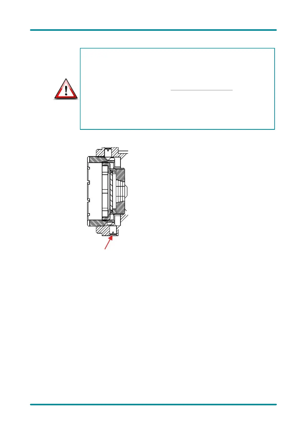
Loosen the locking screw on the bottom of the camera (see illustration
below).
2.
Release the filter holder by turning it two revolutions counterclockwise (IDS
special tool required, see also GigE uEye HE Accessories).
3.
Adjust the C-mount ring. Ensure that the notch of the C-mount ring is precisely
aligned with the locking screw (when viewed from the camera front).
4.
Hold the C-mount ring and screw in the locking screw . Do not use excessive
force.
5.
Turn the filter holder clockwise until tight.
 Loading...