© 2009 IDS Imaging Development Systems GmbH22
User Manual uEye Cameras V3.32
6 Camera Basics
Components of the USB uEye SE/RE cameras
The USB uEye SE and RE cameras have a modular structure consisting of the following
components:
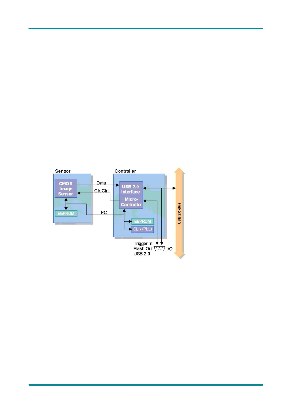
· USB board, including:
§ a USB 2.0 interface which controls data traffic between the camera and the host PC
§ a micro-controller which controls the digital inputs and outputs, the pixel clock and the image
size
§ an EEPROM where the camera manufacturer, type, and serial number are stored
a 64-byte memory area can be used freely by the user
· Sensor board. This board includes:
§ the sensor
§ an EEPROM where the camera type is stored
· Timing board (CCD cameras only)
§ The timing board digitizes the analog output signals of the CCD sensor.
Figure 19: Block diagram of the CMOS USB uEye SE
Components of the USB uEye LE camera
USB uEye LE cameras are equipped with a PCB containing the following components:
· CMOS sensor
· Sensor EEPROM where the camera type is stored.
· USB 2.0 interface which controls data traffic between the camera and the host PC.
· Micro-controller which controls the digital inputs and outputs, the pixel clock and the image size.
· EEPROM where the camera manufacturer, type, and serial number are stored.
A 64-byte memory area can be used freely by the user.
 Loading...