EasyManua.ls Logo

IDS uEye series - Page 202

IDS uEye series
226 pages
Print Icon
To Next Page IconTo Next Page
To Previous Page IconTo Previous Page
Loading...
© 2009 IDS Imaging Development Systems GmbH202
User Manual uEye Cameras V3.32
Pin assignment of the 6-wire connecting cable (6-pin Hirose connector)
Pin
Description
Cable color
1
Ground (GND)
white
2
Power supply (VCC) 12 V
brown
3
Digital input (-)
green
4
Digital input (+)
yellow
5
Digital output (+)
gray
6
Digital output (-)
pink
Figure 189: GigE uEye SE 6-wire cable without AC adapter
(AD.0040.2.18300.00)
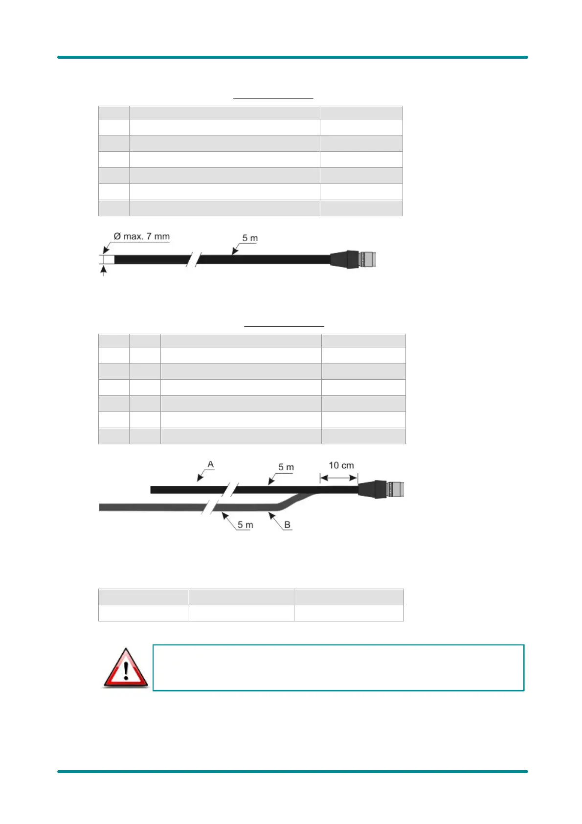
Pin assignment of the 2+4-wire connecting cable (6-pin Hirose connector)
Pin
Cable
Description
Cable color
1
A1
Ground (GND)
white
2
A2
Power supply (VCC) 12 V
brown
3
B1
Digital input (-)
brown
4
B2
Digital input (+)
white
5
B3
Digital output (+)
yellow
6
B4
Digital output (-)
green
Figure 190: GigE uEye SE 2+4-wire cable without AC adapter
(AD.0040.2.18400.00)
Power supply
Voltage
Tolerance
Residual ripple
12 V
+/- 10%
max. 1%
max. 1%
The inrush current of the GigE uEye SE cameras may temporarily increase to up to 2 A.

Table of Contents

Related product manuals