AFL-08B-N270 User Manual
Page 50
Table 2-13: RS-485 Pinouts
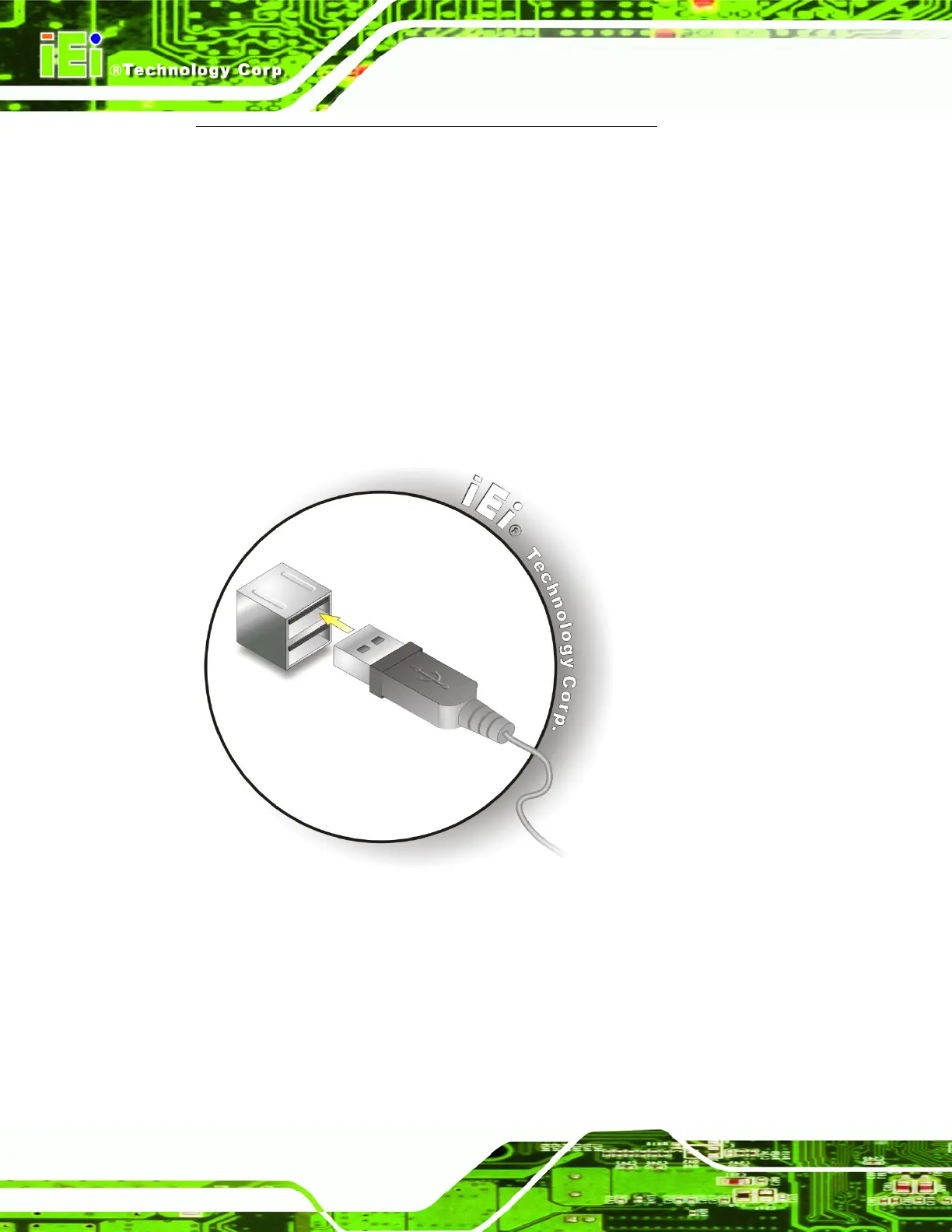
2.7.3 USB Device Connection
There are two external USB 2.0 connectors. To connect a USB 2.0 or USB 1.1 device,
please follow the instructions below.
Step 1: Located the USB connectors. The locations of the USB connectors are shown
in Chapter 2.
Step 2: Align the connectors. Align the USB device connector with one of the
connectors on the bottom panel. See
Figure 2-22.
Figure 2-22: USB Device Connection
Step 3: Insert the device connector. Once aligned, gently insert the USB device
connector into the onboard connector. Step 0:
2.8 Power Connection
The power cable connects the power adapter to the power outlet. The power adapter and
power cable are required for operation of the panel PC.
 Loading...