AFL-08B-N270 User Manual
Page 94
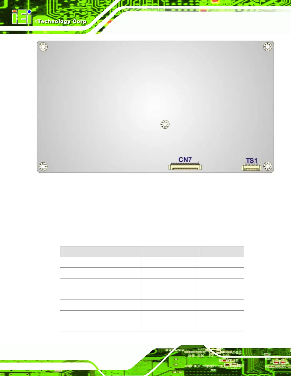
Figure 5-2: Main Board Layout Diagram (Solder Side)
5.2 Internal Peripheral Connectors
Internal peripheral connectors are found on the motherboard and are only accessible
when the motherboard is outside of the chassis. The table below shows a list of the
peripheral interface connectors on the AFL-08B-N270 motherboard. Pinouts of these
connectors can be found in the following sections.
Connector Type Label
AT/ATX switch connector 2-pin header JP4
Audio line-out connector 4-pin wafer CN8
Audio speaker connector 4-pin wafer CN3
Audio MIC-in connector 4-pin wafer MIC1
Audio DMIC-in connector 4-pin wafer DMIC1
Battery connector 2-pin wafer BT1
CF slot CF slot CF1
 Loading...