Platinum™ VX
Installation and Operation Manual Platinum VX Modules
© 2016 Imagine Communications Corp. Proprietary and Confidential. Version 1.2 | Page 54
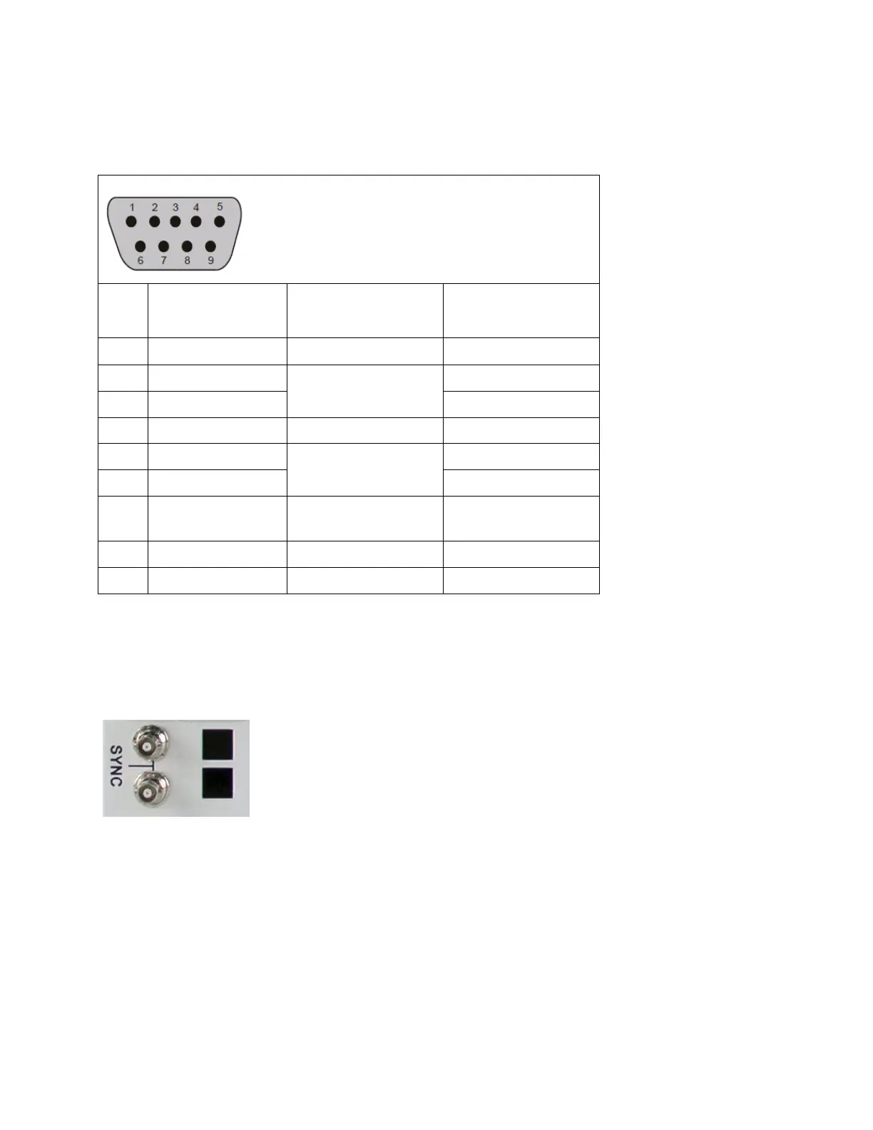
RS-422 Pin Assignments
Table 12: RS-422 Signal Format Pin Assignments
Connection to Remote
Computer (Controller)
Transmitted data
(twisted pair)
Received data
(twisted pair)
Sync Ports
The communications back module on the rear of 4 and 8 RU Platinum VX frames includes a sync port
with looping connectors. Each sync input automatically detects and locks to <NTSC, PAL, analog HD Tri-
Level> signals.
Figure 38: Sync Ports on the rear of 4/8 RU Platinum VX frames
Sync References and Switch Triggering
If no Sync signals are present, the switches occur asynchronously after a reasonable time-out period
(<0.1 seconds from reception of command). If a sync reference was present and is then removed (or
accidentally goes away), the router maintains relative vertical interval switching until a reference is
detected.
The following references can be detected and used to switch the following video standards on the
correct lines as per SMPTE RP168.