C-COM Satellite Systems Inc. Page 85 of 164
position.
Stop Operation
Halts all motor movements and disrupts all communication between iNetVu
®
Mobile System components.
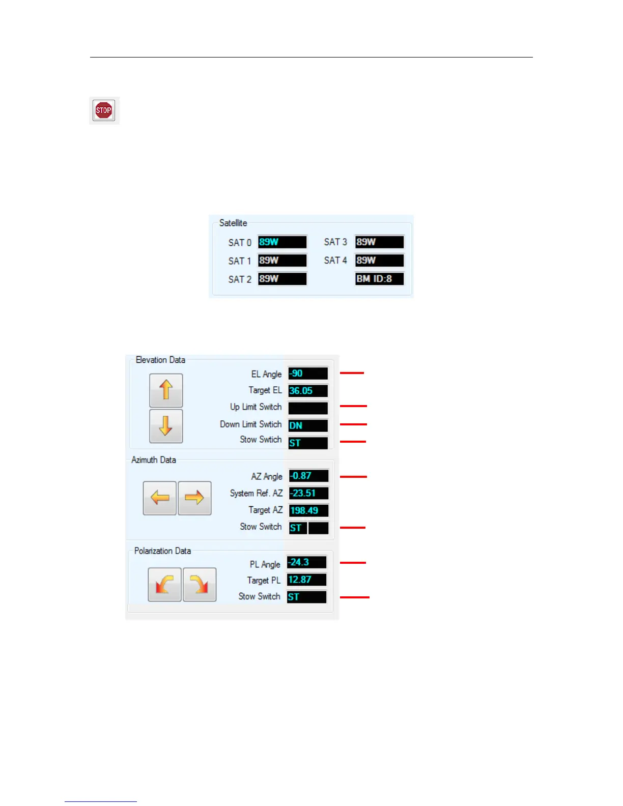
Orbital Slot Location of Configured Satellites
The target and Reference satellites section displays the satellite longitude for each
configured satellite. If no satellites are configured, the default is SAT0. The Beam and or
Carrier will be displayed after the SAT 4 field.
Angle and Limit Switch Indicators
Displays real-time angles and Limit Switch status
Fig. 68: Angle and Limit Switch Indicators
Elevation UP Limit Indicator
Elevation DOWN Limit Indicator
Elevation STOW Limit Indicator
Azimuth STOW (Left/Right) Limit
Indicator
Polarization STOW Limit Indicator