This document contains proprietary and confidential information of Integra LifeSciences Corporation. Integra’s confidential information may not be used, disclosed or reproduced without the prior wrien consent of Integra LifeSciences Corporation.
CUSA® Clarity System Service and Maintenance Manual Page 55 of 117 0645403-2-EN
Voltage Rated Value
actual mains voltage
Frequency Rated Value
actual mains frequency
Equipment Leakage Current =
x actual Leakage Current
x
Example
When the test is performed at 230V/50Hz, and the measured Leakage Current is 50 µA, the Equipment Leakage Current will be:
60 Hz
50 HZ
Equipment Leakage Current = 62,6 µA =
x 50 µA
x
240 V
230 V
7.8.2 Test Conditions
Perform the electrical safety test at the ambient temperature, humidity, and atmospheric pressure at the testing site.
7.8.3 Normalization Instructions
As this test is performed with mains voltage present at the site of testing, measurements have to be normalized before comparing with acceptance
criteria. Normalization is done according to the following formula:
Use a Digital Multi-meter to measure actual voltage.
7.8.4 Test Procedures
Grounding/Earthing System
Obtain the grounding/earthing system information for the electricity supply at the test location (e.g., TN- or IT-System). The type of grounding/earthing
system determines the applicable method used to measure leakage current.
• IT-System is commonly found in the Operating Room environment
• TN-System is normally in the biomedical workshop environment
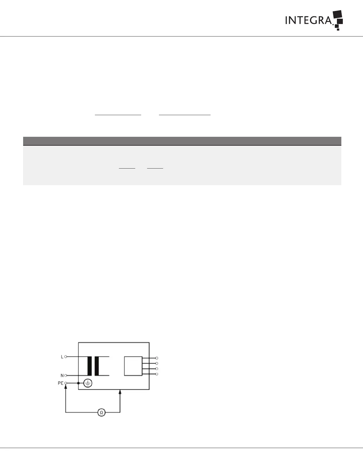
Measurement of Protective Earth Resistance
This test evaluates the integrity the protective earth conductor of the power supply cord and earthing connections of metallic accessible part of
the console and footswitch. During the measurement, the main cord shall be flexed along its length. If during the flexing, changes in resistance are
observed, it shall be assumed that the protective earth conductor is damaged or the connections are no longer adequate.
1. Connect the Safety Analyzer directly to the power source for TN- or IT-Systems.
2. Connect the console to the main socket of Safety Analyzer, and connect the Test Lead to the relevant socket of the Safety Analyzer as
shown in Figure 7-1.
Figure 7-1