EasyManuals Logo

Intel D865PERL User Manual

Intel D865PERL
108 pages
To Next Page IconTo Next Page
To Previous Page IconTo Previous Page
Page #53 background imageLoading...
Page #53 background image
Installing and Replacing Desktop Board Components
53
Connecting the Front Panel Header
Before connecting the front panel header, observe the precautions in Before You Begin on
page 27. Figure 13-D on page 50 shows the location of the front panel header. Table 12 shows the
pin assignments for the front panel header.
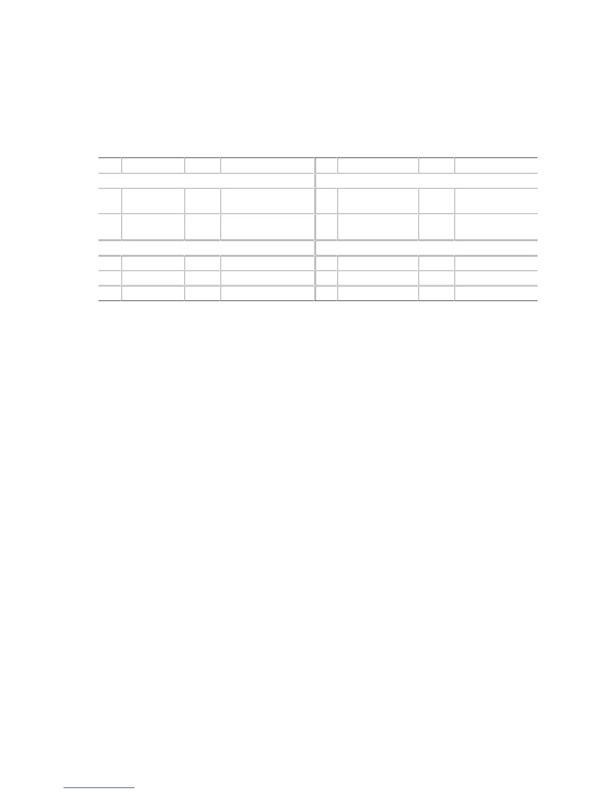
Table 12. Front Panel Header Signal Names (J9G1)
Pin Signal In/Out Description Pin Signal In/Out Description
Hard Drive Activity LED Power LED
1 HD_PWR Out Hard disk LED pull-
up (330 ) to +5 V
2 HDR_BLNK_GRN Out Front panel green
LED
3 HDA# Out Hard disk active LED 4 HDR_BLNK_YEL Out Front panel yellow
LED
Reset Switch On/Off Switch
5 Ground Ground 6 SWITCH_ON# In Power switch
7 FP_RESET# In Reset switch 8 Ground Ground
9 +5 V Out Power 10 N/C Not connected

Table of Contents

Other manuals for Intel D865PERL

Questions and Answers:

Question and Answer IconNeed help?

Do you have a question about the Intel D865PERL and is the answer not in the manual?

Intel D865PERL Specifications

General IconGeneral
ChipsetIntel 865PE
SocketSocket 478
Form FactorATX
Memory TypeDDR SDRAM
Memory Slots4
Maximum RAM4 GB
Expansion Slots1 x AGP 8x, 5 x PCI
LAN10/100 Mbps Ethernet
Supported CPUIntel Pentium 4, Intel Celeron
Storage Interfaces2 x ATA-100, 2 x SATA
USB Ports8 x USB 2.0 (4 rear, 4 via headers)
Audio6-channel AC'97

Related product manuals