A SQUALL II MODULE INTERFACE
5-7
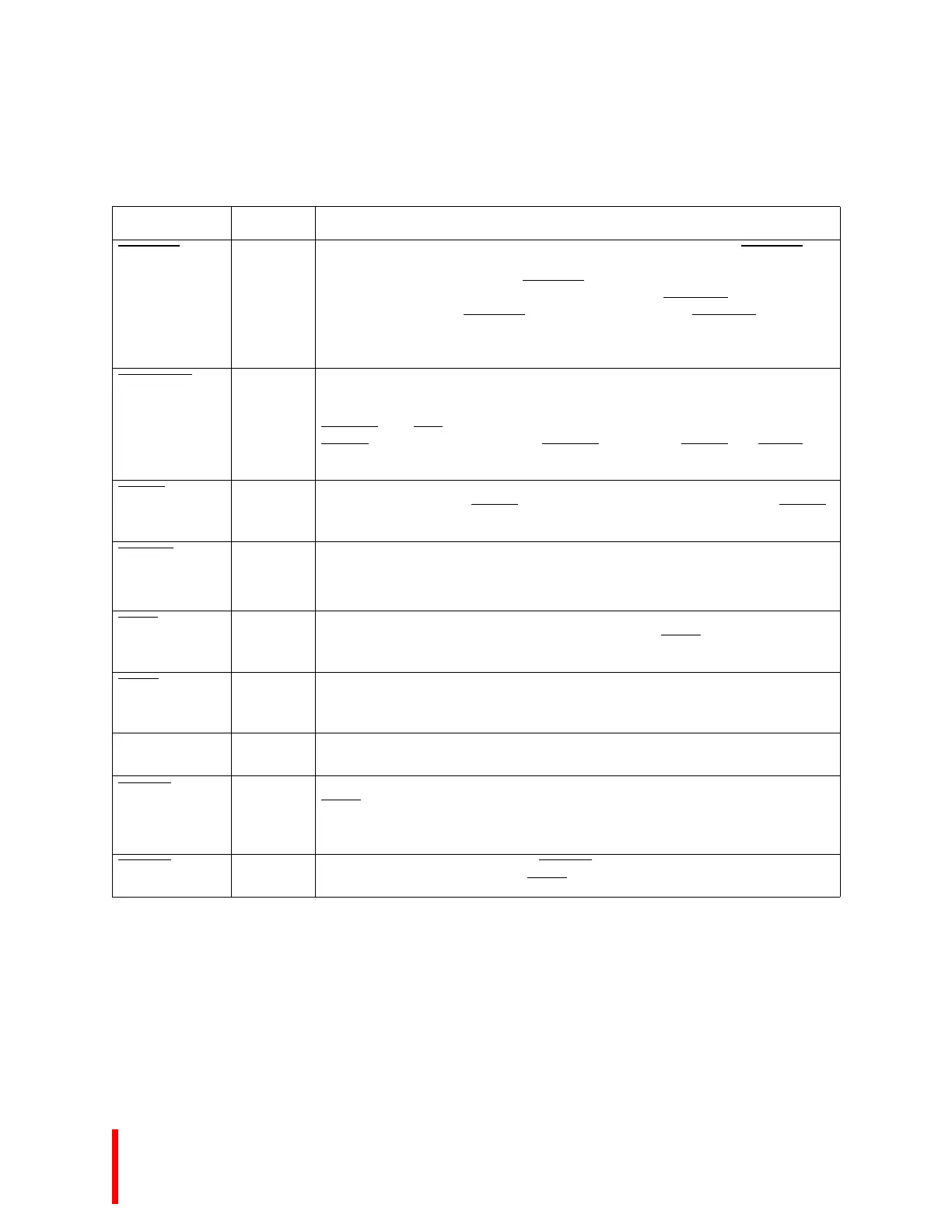
S_BLAST SL(I)
M(O)
S
Burst Last indicates the last transfer in a bus access. In slave mode S_BLAST is
asserted in the data transfer of burst and non-burst accesses after the processor’s
wait state counter reaches zero. S_BLAST
remains active until the clock following
the last cycle of the last data transfer of a bus access. If S_READY
signal is used to
extend wait states, the S_BLAST
signal remains active until S_READY terminates
the access. In master mode, this signal should be used to indicate to the shared
memory the last cycle of a burst access.
S_EXTEND
SL(I)
M(O)
S
Extend may be used by slow Squall II Module masters to extend a shared memory
read or write cycle. Extend has no meaning for slaves and will always be inactive
during slave cycles. Non-burst reads of the DRAM may be extended by asserting
EXTEND
after ADS. The DRAM controller will hold valid data on the bus and the
READY
signal active until it detects EXTEND inactive and READY and BLAST
asserted. The signal should not be asserted on burst or write cycles.
RESET
I
A
Reset asserted should cause all the devices and circuitry on the Squall II Module to
return to a known state. RESET
will be asserted for a minimum of 200ms. RESET
will always be asserted following power-up.
S_LOCK
SL(I)
M(O)
S
Bus Lock indicates that an atomic ready-modify-write operation is in progress.
SQBR
O Shared Bus Request signals that the Squall II Module circuitry requested access to
the shared memory. The local bus arbitrator will assert SQBG
to grant the Squall II
Module bus mastership.
SQBG
I
S
Shared Bus Grant indicates to a bus requestor that the other shared bus masters
have relinquished control of the bus. The Squall II Module circuitry may now use
the shared bus to access the on board shared memory.
PMCLK
I CPU Module Output Clock provides a timing reference for all input and output to the
processor and the memory.
SQIRQ0
O Interrupt Request 0 is directly connected to the processor’s external interrupt pin
XINT4
. This pin may be programmed within the processor as a level (low) or edge
(falling) activated interrupt source. The interrupt priority of this pin may also be
programmed within the processor.
SQIRQ1
O Interrupt Request 1 is the same as SQIRQ0 except that it is connected to the
processor’s external interrupt pin XINT3
.
Table 5-3. Squall Module Signal Descriptions (Sheet 3 of 3)
Name Type Description