SQUALL II MODULE INTERFACE A
5-6
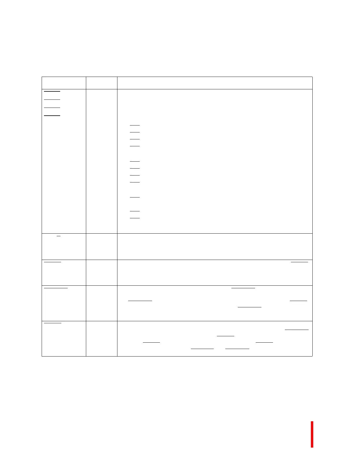
S_BE3
S_BE2
S_BE1
S_BE0
SL(I)
M(O)
S
Byte Enables select which of the four bytes addressed by A[02:31] are active
during an access to a memory region configured as 32 bits data bus width. The
following describes the usage of the Byte Enable Signals in different data bus
configurations.
32 bit bus:
BE3
Byte Enable 3 - Enable D[24:31]
BE2
Byte Enable 2 - Enable D[16:23]
BE1
Byte Enable 1 - Enable D[08:15]
BE0
Byte Enable 0 - Enable D[00:07]
16 bit bus:
BE3
Byte High Enable - Enable D[08:15]
BE2
Not Used
BE1
Address bit 1 - A[01]
BE0
Byte Low Enable - Enable D[00:07]
8 bit bus:
BE3
Not Used
BE2 Not Used
BE1
Address Bit 1 - A[01]
BE0
Address Bit 0 - A[00]
Note: 16 and 8 bit bus modes are not available with Kx or Sx processor modules.
S_W/R
SL(I)
M(O)
S
Write/Read is low for read accesses and high for write accesses. The operation
(read or write) is relative to the bus master.
S_ADS
SL(I)
M(O)
S
Address Strobe indicates valid address and the start of a new bus access. S_ADS
is asserted for the first clock of an access.
S_READY
SL(O)
M(I)
S
Ready signals the termination of a data transfer. S_READY is used to indicate that
read data on the bus is valid or that write data transfer is completed. In slave mode,
the S_READY
signal should be asserted to terminate a cycle indicated by SQSEL.
In master mode, the memory control circuit asserts S_READY
to indicate that valid
read data is on the data bus or that a write transfer is complete.
SQSEL
I
S
Select Squall is a select signal for a processor’s 256 Mbyte memory region. The
memory region base address is C000 0000H. The designer must return S_READY
to the processor when this signal is active. SQSEL
is asserted on the rising edge of
PMCLK if S_ADS
is asserted and A[28:31] = C000 0000H. SQSEL is negated on
the rising edge of PMCLK with S_BLAST
and S_READY asserted.
Table 5-3. Squall Module Signal Descriptions (Sheet 2 of 3)
Name Type Description