154 Intel
®
Modular Server System Service Guide
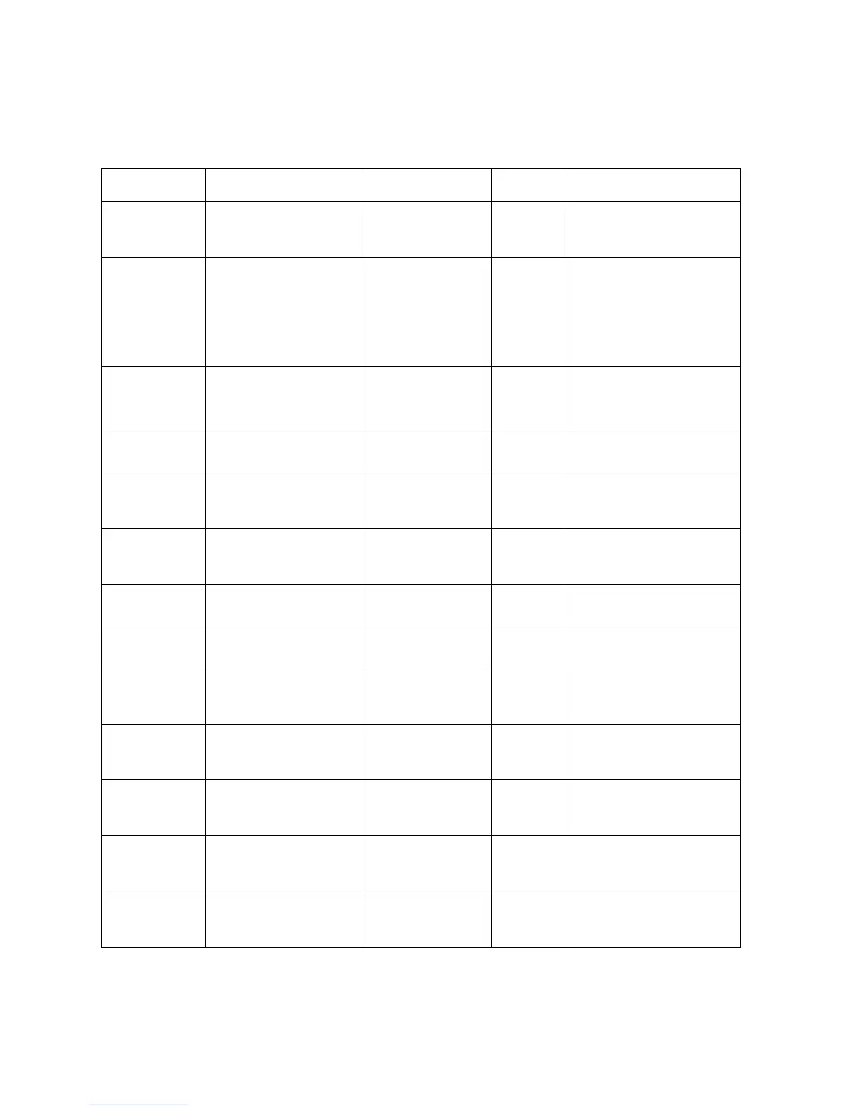
Table 32. Diagnostic LEDs
LED Name Function Location Color Indicator
Chassis ID LED Aids in server
identification from the
back panel
Chassis front Blue Press ID LED button or use
Management Module UI
software to turn off the LED.
System Fault
LED
Visible fault warning Chassis front Amber Green = No Fault
Green Blink = Degraded
Amber = Critical error or
non-recoverable
Amber blink = Non-critical
Hard Drive
Power/Activity
LED
Identifies the power state
of the hard drive, indicate
drive activity
Hard drive carrier
front panel
Green On = Hard drive power on
Green Blink = Hard drive
activity
Hard Drive
Fault LED
Visible fault warning Hard drive carrier
front panel
Amber On = Hard drive fault
I/O Cooling
Module Power
LED
Identifies the power state
of the I/O cooling module
I/O cooling module
front panel
Green On = Cooling module power
on
I/O Cooling
Module Fault
LED
Visible fault warning I/O cooling module
front panel
Amber On = I/O cooling module
fault
Fan Module
Power LED
Identifies the power state
of the fan module
Fan module front
panel
Green On = Fan module power on
Fan Module
Fault LED
Visible fault warning Fan module front
panel
Amber On = Fan module fault
Storage Control
Module Power
LED
Identifies the power state
of the storage control
module
Storage control
module front panel
Green On = Storage control module
power on
Storage Control
Module Fault
LED
Visible fault warning Storage control
module front panel
Amber On = Storage control module
fault
Storage Control
Module Dirty
Cache LED
Identifies the state of
storage control module
cache
Storage control
module front panel
Green Slow blink = Dirty cache
Ethernet Switch
Module Power
LED
Identifies the power state
of the Ethernet switch
module
Ethernet switch
module front panel
Green On = Ethernet switch module
power on
Ethernet Switch
Module Fault
LED
Visible fault warning Ethernet switch
module front panel
Amber On = Ethernet switch module
fault