EasyManua.ls Logo

Intel QX9770 - Core 2 Extreme Quad-Core Processor User Manual

Intel QX9770 - Core 2 Extreme Quad-Core Processor
123 pages
To Next Page IconTo Next Page
To Previous Page IconTo Previous Page
Page #83 background imageLoading...
Page #83 background image
Case Temperature Reference Metrology
Thermal and Mechanical Design Guidelines 83
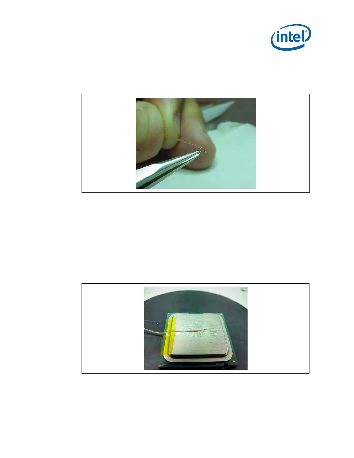
5. Using the microscope and tweezers, bend the tip of the thermocouple at
approximately 10 degree angle by about 0.8 mm [.030 inch] from the tip
(
Figure 36).
Figure 36. Bending the Tip of the Thermocouple
D.5.2 Thermocouple Attachment to the IHS
6. Clean groove and IHS with Isopropyl Alcohol (IPA) and a lint free cloth removing
all residues prior to thermocouple attachment.
7.
Place the thermocouple wire inside the groove; letting the exposed wire and bead
extend about 1.5 mm [0.030 inch] past the end of groove. Secure it with Kapton*
tape (
Figure 37). Clean the IHS with a swab and IPA.
8. Verify under the microscope that the thermocouple wires are straight and parallel
in the groove and that the bead is still bent.
Figure 37. Securing Thermocouple Wires with Kapton* Tape Prior to Attach

Table of Contents

Question and Answer IconNeed help?

Do you have a question about the Intel QX9770 - Core 2 Extreme Quad-Core Processor and is the answer not in the manual?

Intel QX9770 - Core 2 Extreme Quad-Core Processor Specifications

General IconGeneral
Processor NumberQX9770
Number of Cores4
Thread Count4
Clock Speed3.2 GHz
L2 Cache12 MB
Bus Speed1600 MHz
Thermal Design Power (TDP)136 W
SocketLGA 775
Manufacturing Process45 nm
Max Operating Temperature64.5°C
Virtualization TechnologyYes
64-bit SupportYes
Instruction SetSSE4.1
Memory Channels2
Memory TypesDDR3

Summary

2 Processor Thermal/Mechanical Information

2.1 Mechanical Requirements

Details the physical and mechanical specifications for the processor.

2.2 Thermal Requirements

Outlines the thermal specifications like Thermal Profile and TCONTROL.

2.3 Heatsink Design Considerations

Factors to consider for heatsink design, including surface area and conduction.

3 Thermal Metrology

3.1 Characterizing Cooling Performance Requirements

Defines thermal characterization parameters like Psi (Ψ) for performance assessment.

3.2 Processor Thermal Solution Performance Assessment

Recommends using a Thermal Test Vehicle (TTV) for performance assessment.

3.3 Local Ambient Temperature Measurement Guidelines

Provides guidelines for measuring local ambient temperature accurately.

3.4 Processor Case Temperature Measurement Guidelines

Details procedures for accurate measurement of processor case temperature.

4 Thermal Management Logic and Thermal Monitor Feature

4.2 Thermal Monitor Implementation

Details the components and functionality of the on-die thermal monitor.

4.2.1 PROCHOT# Signal

Explains the PROCHOT# signal for indicating thermal excursions.

4.2.2 Thermal Control Circuit

Describes the TCC's role in reducing power to manage temperature.

4.2.3 Thermal Monitor 2

Details the enhanced Thermal Monitor 2 capabilities for power reduction.

4.2.4 Operation and Configuration

How the Thermal Monitor is enabled and configured via BIOS.

4.2.8 THERMTRIP# Signal

Explains the THERMTRIP# signal for catastrophic cooling failure.

4.2.10 Digital Thermal Sensor

Discusses the DTS for fan speed control and its relation to TCONTROL.

5 Intel Thermal/Mechanical Reference Design Information

5.4 Safety Requirements

Outlines safety certifications and requirements for components.

6 Intel® Quiet System Technology (Intel® QST)

6.1 Intel® Quiet System Technology Algorithm

Explains the QST algorithm using PID control and a weighting matrix.

Appendix A LGA775 Socket Heatsink Loading

Appendix B Heatsink Clip Load Metrology

Appendix C Thermal Interface Management

C.3 Interface Material Performance

Details factors affecting TIM performance: thermal resistance and wetting.

Appendix D Case Temperature Reference Metrology

D.5 Thermocouple Attach Procedure

Step-by-step guide for attaching a thermocouple using solder.

D.5.2 Thermocouple Attachment to the IHS

Step-by-step process for attaching the thermocouple to the IHS.

D.5.3 Solder Process

Describes the soldering process to attach the thermocouple bead.

Appendix E Legacy Fan Speed Control

E.4 Interaction of Thermal Profile and TCONTROL

Explains how thermal profile and TCONTROL dictate fan speed.

Related product manuals