Case Temperature Reference Metrology
84 Thermal and Mechanical Design Guidelines
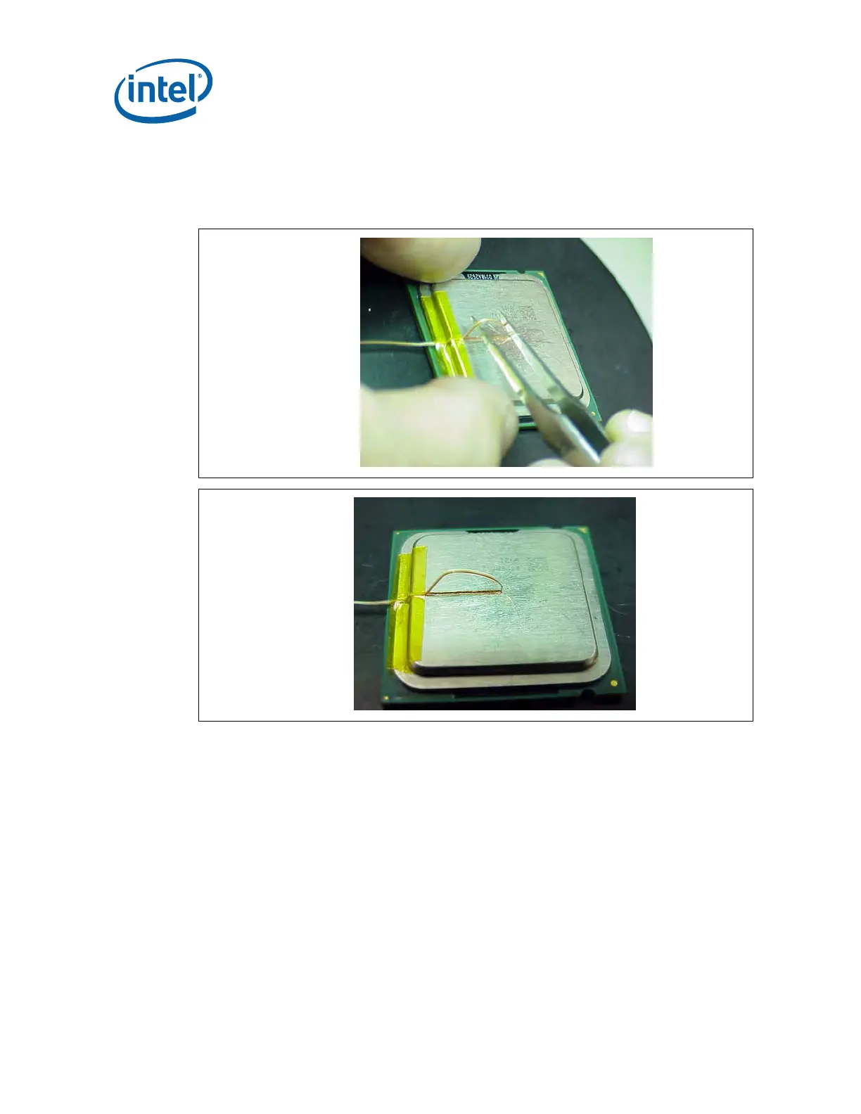
9. Lift the wire at the middle of groove with tweezers and bend the front of wire to
place the thermocouple in the groove ensuring the tip is in contact with the end
and bottom of the groove in the IHS (
Figure 38-A and B).
Figure 38. Thermocouple Bead Placement
(A)
(B)
10. Place the package under the microscope to continue with process. It is also
recommended to use a fixture (like processor tray or a plate) to help holding the
unit in place for the rest of the attach process.