Legacy Fan Speed Control
106 Thermal and Mechanical Design Guidelines
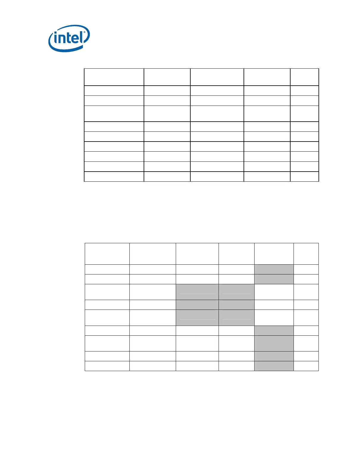
Table 13. ATX FSC Settings
Parameter Classification Processor
Thermal Sensor
PWM Output Notes
T
HIGH
Required T
CONTROL
3
T
LOW
Required T
CONTROL
– 10 °C 3
Minimum PWM Duty
Cycle
Required 20%
PWM Frequency Required 21-28 kHz 1
Spin-up time Suggested 250 - ~500 ms 2, 4
T
AVERAGING
Suggested 35 sec 4
When T
SENSOR
< T
LOW
Suggested Minimum PWM%
All Fans ON Suggested T
CONTROL
+ 3 °C
Hysteresis Suggested 2 °C
NOTES:
1. A PWM frequency of 25 kHz is the design target for the reference and for the Intel
®
Boxed Processor and the reference design..
2. Use the lowest time available in this range for the device selected.
3. To ensure compliance with the thermal specification, thermal profile and usage of the
T
SENSOR
for fan speed control these setting should not be user configurable.
4. If this function is present on the device it must be enabled
Table 14. BTX Fan Speed Control Settings
Parameter Classification Processor
Thermal
Sensor
System
Ambient
Sensor
PWM
Output
Notes
T
HIGH
Required T
CONTROL
54 °C 3,5
T
LOW
Required T
CONTROL
– 7 °C 47 °C 3,5
Minimum PWM
Duty Cycle
Required PWM 1
(TMA) –20%
PWM Frequency Required 21-28 kHz 1
Spin Up Time Suggested 250 –
~ 500 ms
2, 7
T
AVERAGING
Suggested 4.0 sec 4.0 sec 3, 7
When T
SENSOR
<
T
LOW
Suggested Minimum
PWM%
Minimum
PWM%
All Fans On Suggested T
CONTROL
+ 3 °C 65 °C
Hysteresis Suggested 2 °C 4 °C
NOTES:
1. A PWM frequency of 25 kHz is the design target for the reference and for the Intel
®
Boxed Processor and the reference design.
2. Use the lowest time available in this range for the device selected
3. T
AVERAGING
= represents the amount of delay time before responding to the temperature
change, defined in fan speed control device (sometimes called ramp range control or