92 Intel Server Board SCB2 Product Guide
Diagnostic LEDs
To help diagnose POST failures, a set of four bi-color diagnostic LEDs is located on the back edge
of the baseboard. Each of the four LEDs can have one of four states: Off, Green, Red, or Amber.
The LED diagnostics feature consists of a hardware decoder and four dual color LEDs. During
POST, the LEDs will display all normal Port80 codes representing the progress of the BIOS POST.
Each postcode will be represented by a combination of colors from the 4 LEDs. The LEDs are in
pairs of green and red. The post codes codes are broken into two nibbles, an upper and a lower
nibble. Each bit in the upper nibble is represented by a red LED and each bit in the lower nibble is
represented by a green LED. If both bits are set in the upper and lower nibble then both red and
green LEDs are lit, resulting in an amber color. Likewise, if both bits are clear then the red and
green LEDs are off.
During the POST process, each light sequence represents a specific Port-80 POST code. If a
system should hang during POST, the Diagnostic LEDs will present the last test executed before
the hang. When reading the lights, the LEDs should be observed from the back of the system. The
most significant bit (MSB) is the first LED on the left, and the least significant bit (LSB) is the last
LED on the right.
Note: When comparing a diagnostic LED color string from the baseboard to those listed in the
diagnostic LED decoder in the following tables, the LEDs on the baseboard should be referenced
when viewed by looking into the system from the back. Reading the LEDs from left to right, the Hi
bit is located on the left.
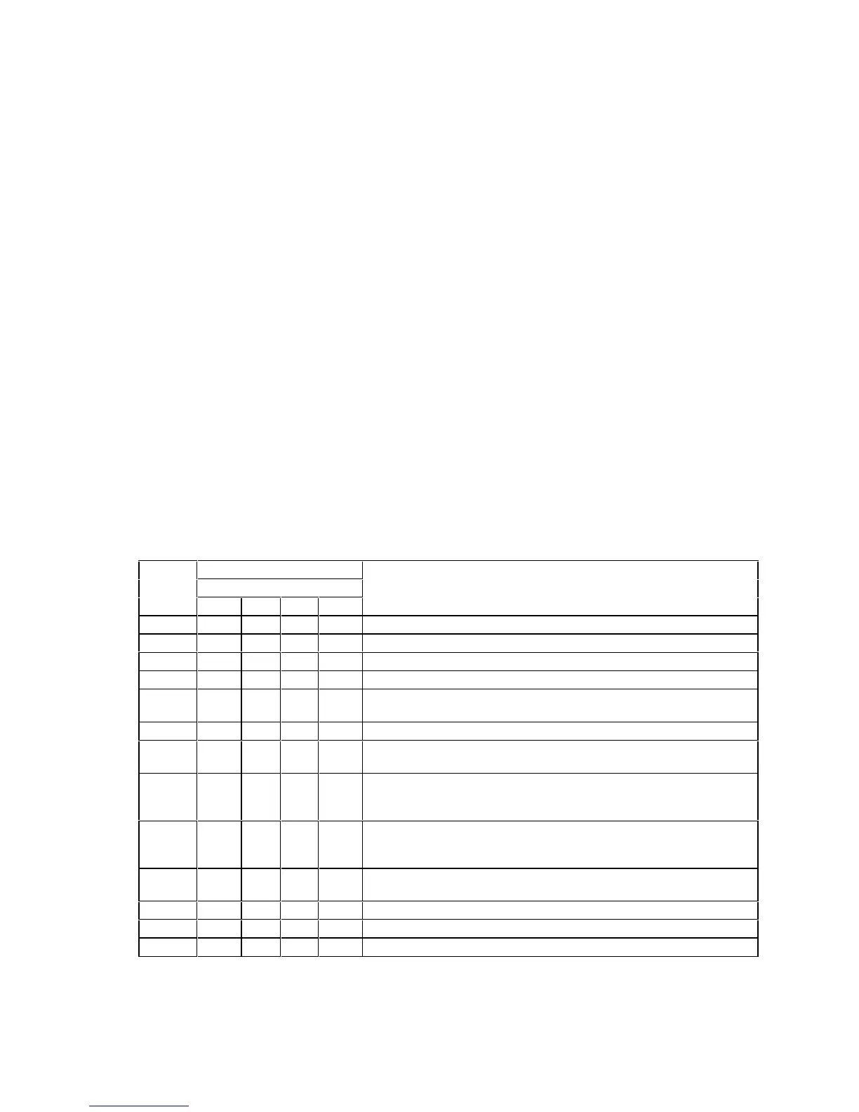
Table 11. Post Codes
Diagnostic LED Decoder
G=Green, R=Red, A=Amber
Post
Code
MSB LSB
Description
07h Off G G G Uncompress various BIOS Modules
08h G Off Off Off Verify password Checksum
08h G Off Off Off Verify CMOS Checksum.
07h Off G G G Read Microcode updates from BIOS ROM.
07h Off G G G
Initializing the processors. Set up processor registers. Select least
featured processor as the BSP.
0Bh G Off G G Hook before the keyboard BAT command is issued.
0Ch G G Off Off
Keyboard Controller Test: The keyboard controller input buffer is
free. Next, issuing the BAT command to the keyboard controller
0Eh G G G Off
Init after Keyboard Test: The keyboard controller BAT command
result has been verified. Next, performing any necessary
initialization after the keyboard controller BAT command test.
0Fh G G G G
Write Command Byte 8042: The initialization after the keyboard
controller BAT command test is done. The keyboard command byte
will be written next.
10h Off Off Off R
Keyboard Init: The keyboard controller command byte is written.
Next, issuing the pin 23 and 24 blocking and unblocking commands
10h Off Off Off R Disable and initialize 8259
11h Off Off Off A Detect Configuration Mode, such as CMOS clear.
13h Off Off G A Chipset Initialization before CMOS initialization
continued

 Loading...


