8 Intel Server Board SCB2 Product Guide
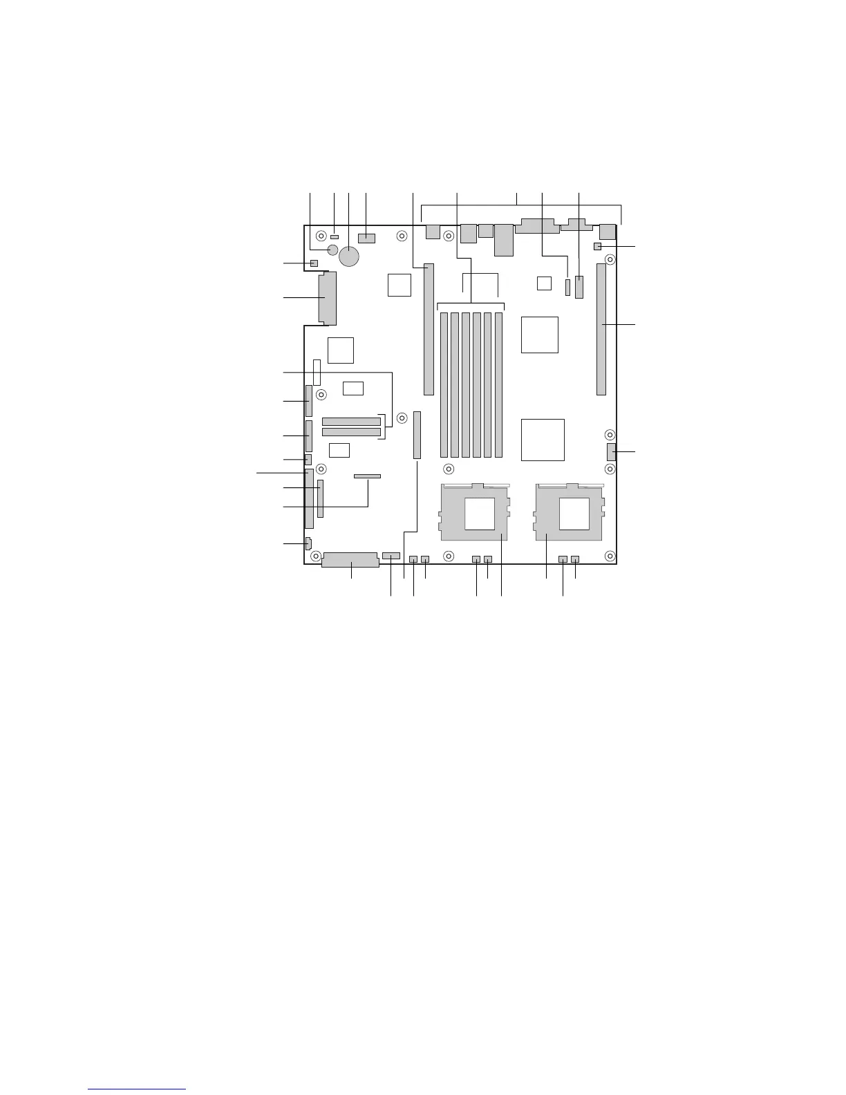
Server Board Connector and Component Locations
The SCB2 comes in both SCSI and ATA versions. Figure 1 is a composite view of both versions.
OM11707
G
IF H
K
L
OW M
NP
Q
R
SU
TV
BB
AA
X
A C D E
FF
DD
CC
EE
B
Y
Z
J
GG
A. Speaker
B. ID LED
C. Battery
D. Diagnostic LEDs (POST code)
E. 66 MHz/64-bit PCI riser slot (full height)
F. DIMM slots
G. I/O ports
H. ICMB connector
I. COM 1 serial header
J. Chassis intrusion connector
K. 66 MHz/64-bit PCI riser slot (low profile)
L. USB 3 & 4 header
M. Sys fan 3 connector
N. CPU 2 fan connector
O. Secondary processor socket
P. Primary processor socket
Q. Sys fan 2 connector
R. CPU 1 fan connector
S. Sys fan 1 connector
T. Aux fan connector
U. Floppy drive connector
V. Fan module connector
W. Main power connector
X. Auxiliary signal connector
Y. Floppy/FP/IDE connector
Z. Alternate front panel connector
AA. ATA/IDE connector
BB. IPMB connector
CC. SSI front panel connector
DD. Configuration jumper block
EE. ATA-100 connectors (ATA version only)
FF. SCSI connector (SCSI version only)
GG. Hard Disk Drive LED header
Figure 1. Server Board Connector and Component Locations

 Loading...


