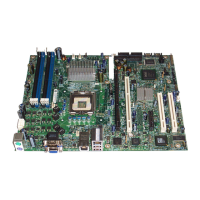
Description
15
Memory
The Intel
®
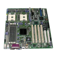
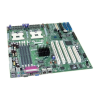
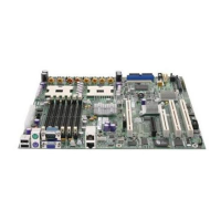
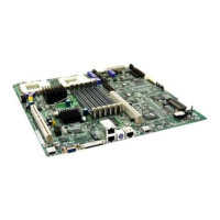
Server Board SE7501HG2 contains six 184-pin DIMM sockets and provides support for
up to 12 GB of memory. The memory subsystem provides dual memory bus architecture; the
memory on the board is partitioned into three banks of DDR DIMMs. DIMMs must be installed in
pairs, providing a 144-bit wide data path via three separate memory buses. DIMMs must also be
installed in order by Bank. Bank 1 must be filled before populating Bank 2. Bank 2 must be
populated before installing DIMMs in Bank 3.
The memory controller supports 2-way interleaved SDRAM, memory scrubbing, single-bit error
correction and multiple-bit error detection with the Intel x4 Single Device Data Correction
capability that allows the system to continue to run even in the event of a multi-bit SDRAM failure.
Memory can be implemented with either single-sided (one row) or double-sided (two row) DIMMs.
The server board supports up to six ECC DDR DIMMs that are compliant with the JEDEC DDR
266 specification. A wide range of DIMM sizes are supported, including:
• 128 MB
• 256 MB
• 512 MB
• 1 GB
• 2 GB
The minimum supported memory configuration is 256 MB, using two 128 MB DIMMs. The
maximum configurable memory size is 12 GB using six 2 GB DIMMs. Each DIMM within a bank
must be identical, but each bank can use different sized DIMMs. For example, Bank 1 can have
two 128 MB DIMMs installed and Bank 2 can have two 256 MB DIMMs installed. DIMMs from
different vendors can be used, but is not recommended because the system defaults to the slowest
speed that will work with all of the vendors’ DIMMs.
✏
NOTE
Use DIMMs that have been tested for compatibility with the server board.
Check the Intel Customer Support website for the latest tested memory list:
http://support.intel.com/support/motherboards/server/SE7501HG2
PCI I/O Subsystem
The SE7501HG2 server board provides three PCI bus segments:
• Segment C with one PCI-X 64-bit / 133 MHz slots (Slot 1)
• Segment B with two PCI-X 64-bit / 100 MHz slots (Slots 2
3
and 3)
• Segment A with three PCI 32-bit / 33 MHz slots (Slots 4, 5, and 6)
The least capable card installed on a segment determines the bus mode/speed. In other words, the
segment will run at the speed of the slowest installed card.
3
Slot 2 supports Zero Channel RAID
 Loading...
