Intel Server Board SE7501HG2 Product Guide
44
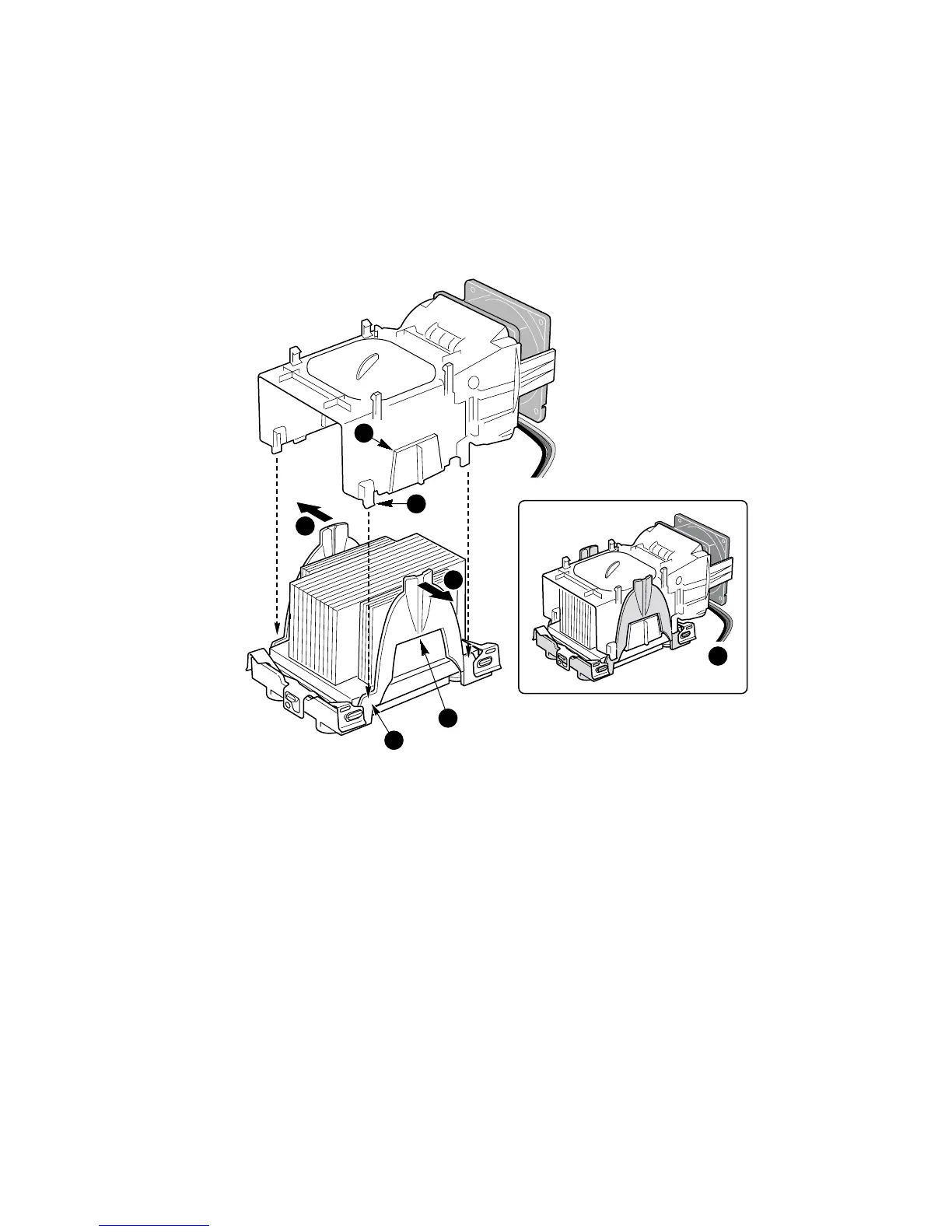
14. Attach the fan assembly to the retention mechanism. Pull the tabs at the sides of the retention
mechanism apart slightly. See Figure 15, 1. Lower the fan assembly into the retention
mechanism. The tabs on the fan assembly (Figure 15, 3) will fit into the slots of the retention
mechanism (Figure 15, 1). Pull out on the tabs located at the bottom of the fan assembly to
snap them into place on the OUTSIDE of the retention mechanism (Figure 15, 2).
15. Attach CPU Fan 1 cable to the server board at location J7F1 and/or attach CPU Fan 2 cable at
location J5F1. (Figure 15, 4.)
2a
2b
3b
OM15045
1
1
3a
4
Figure 15. Attaching the Top Assembly to the Retention Mechanism
✏
NOTE
System airflow must be from front to back. Make sure the PWT is aligned so
the fan is toward the front of the chassis and the airflow is toward the I/O
shield. If two processors are installed, the fans will be side by side.