36
C700 - Marine Satellite Communication System
RJ45 Connector
Pin Signal
1 TD+
2 TD-
3 RD+
4 NC
5 NC
6 RD-
7 NC
8 NC
6.8 BDU Connector Pinout Guide
The BDU connector pins and their corresponding descriptions are shown in the following gures and tables
6.8.1 LAN Ports (RJ45)
Figure 30: LAN Ports (RJ45) Pinout
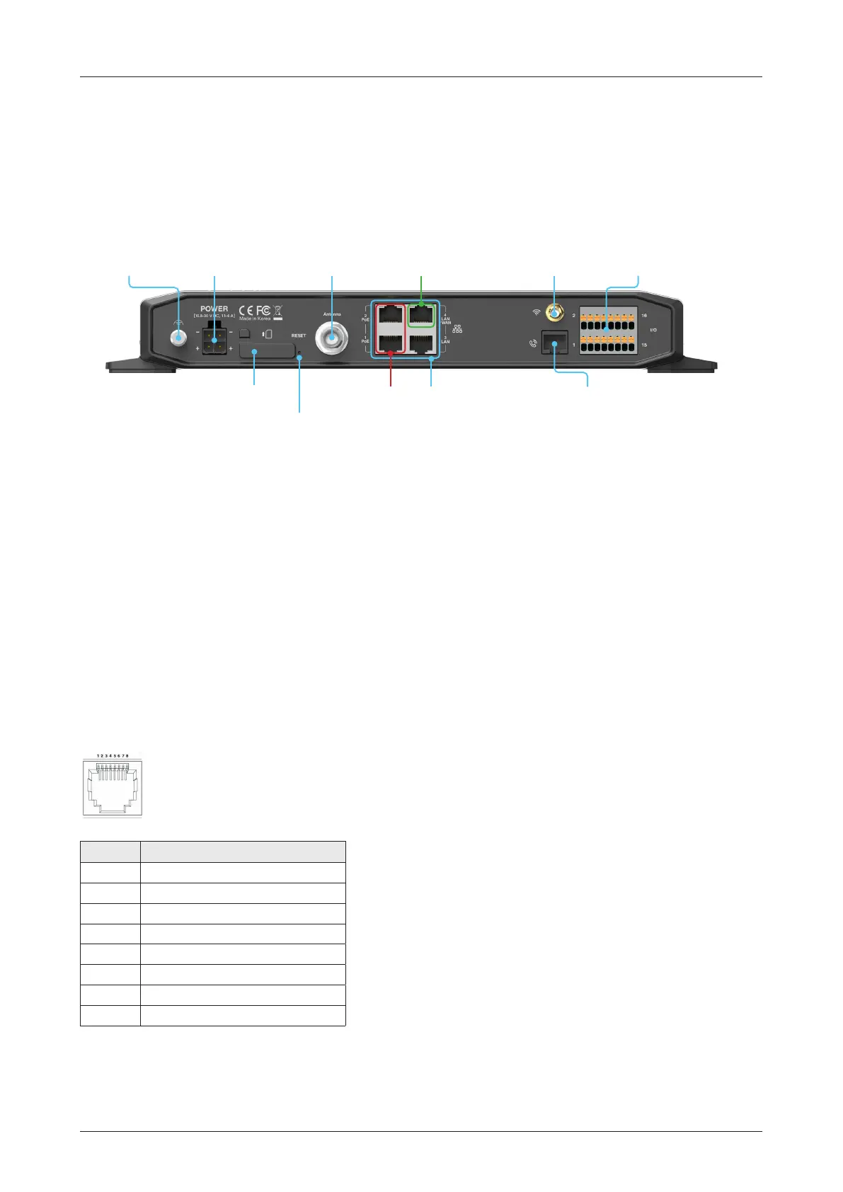
6.7 BDU Cable Connection
6.7.1 BDU Back Panel View
The following gure shows the BDU back panel.
Figure 29: BDU Back Panel View
* All LAN ports are IEEE 802.3 compliant.
** Each PoE Port is designed to use 7.5W power. When using over
12.5W in one port, the PoE function will be stopped in port 1 or port 2.
*LAN Port 1, 2,
3, 4 (RJ45) for
SIP Phones or
Computers
SIM Card Slot
Reset Button
Phone Port (RJ14)
for POTS (Plain Old
Telephone Service)
Antenna
Connector (TNC)
WAN (Wide Area
Network) Port
Power
Connector
Grounding
Stud
Wi-Fi
Connector
GPIO
Connector
**PoE (Power
over Ethernet)
Port 1, 2 (RJ45)

 Loading...