37
Installing BDU
RJ14 & 6P4C (6-Positions 4-Contacts)
Pin Signal
1 N/A
2 T2+ (POTS Phone 2, no. 102)
3 R1- (POTS Phone 1, no. 101)
4 T1+ (POTS Phone 1, no. 101)
5 R2- (POTS Phone 2, no. 102)
6 N/A
Figure 31: Phone Port (RJ14 & 6P4C) Pinout
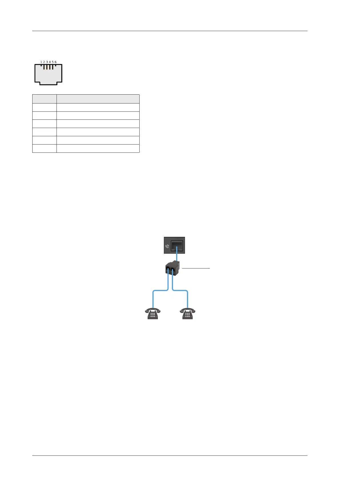
6.8.2 Phone Port (RJ14 & 6P4C)
When connecting RJ14 phones, it is recommended to use a separate cable splitter (customer supplied).
The POTS phone 1 (no. 101) is connected to a pair of Pin 3 (R1-) and Pin 4 (T1+) wires. The POTS phone 2
(no. 102) is connected to a pair of Pin 5 (R2-) and Pin 2 (T2+) wires.
Figure 32: Using Cable Splitter with RJ14 Phones
Phone (RJ14)
Cable Splitter
POTS
Phone 1
(no. 101)
POTS
Phone 2
(no. 102)
Pin 5 (R2-) &
Pin 2 (T2+)
Pin 3 (R1-) &
Pin 4 (T1+)

 Loading...